Safety catch connector

a safety belt and connector technology, applied in the direction of safety belts, fastening means, shackles, etc., can solve the problems of unavoidable lugs, significant increase of notch, and unavoidable lugs, so as to prolong the life of the safety belt and save the operation time of locking and unlocking.

Active Publication Date: 2016-09-06
AKILA TECH CO LTD
View PDF6 Cites 17 Cited by
  • Summary
  • Abstract
  • Description
  • Claims
  • Application Information

AI Technical Summary

Benefits of technology

[0015]Therefore, the size of the notch of the present invention can be enlarged at the distance between the first sleeve and the second sleeve, such that the safety belt and the lifting lug of the catch device can be easily accessed through the enlarged notch via the coupling and decoupling operations. It further controls the sliding movement of the locking shaft at the first sleeve hole and the second sleeve hole through the first controlling unit and the second controlling unit to save the operational time of locking and unlocking operation of the present invention. Besides, the locking shaft is long enough that the safety belt can be directly wound around the locking shaft while the lifting lug of the catch device is held at the retention arm, such that the safety belt will not be directly contacted with the lifting lug of the catch device. In other words, the metal lifting lug will keep away from the safety belt to prevent the safety belt from being worn or hit by the lifting lug, so as to greatly prolong the life span of the safety belt.

Problems solved by technology

Firstly, the connector generally comprises an arc-shaped ring member having a notch, and a sleeve member rotatably coupled at the ring member to selectively close or open the notch for holding the tools. Accordingly, if the notch is too big, the operation time for rotating the sleeve member to close or open the notch will be significantly increased. It the notch is too small, it is difficult for the user to quickly couple the tool with the connector through the notch. Therefore, it is always arguable to configure the opening size of the notch to enhance the operation of the sleeve member and to enable the quick access of the connector.
Secondly, the connector of the prior invention cannot sort out different tools, such as the lifting lug of the catch device and a safety belt, so that the lifting lug will unavoidably contact with the safety belt which will wear the safety belt and shorten the life span thereof.

Method used


Image

  • Safety catch connector
  • Safety catch connector
  • Safety catch connector

Examples


Embodiment Construction

[0026]The following description is disclosed to enable any person skilled in the art to make and use the present invention. Preferred embodiments are provided in the following description only as examples and modifications will be apparent to those skilled in the art. The general principles defined in the following description would be applied to other embodiments, alternatives, modifications, equivalents, and applications without departing from the spirit and scope of the present invention.

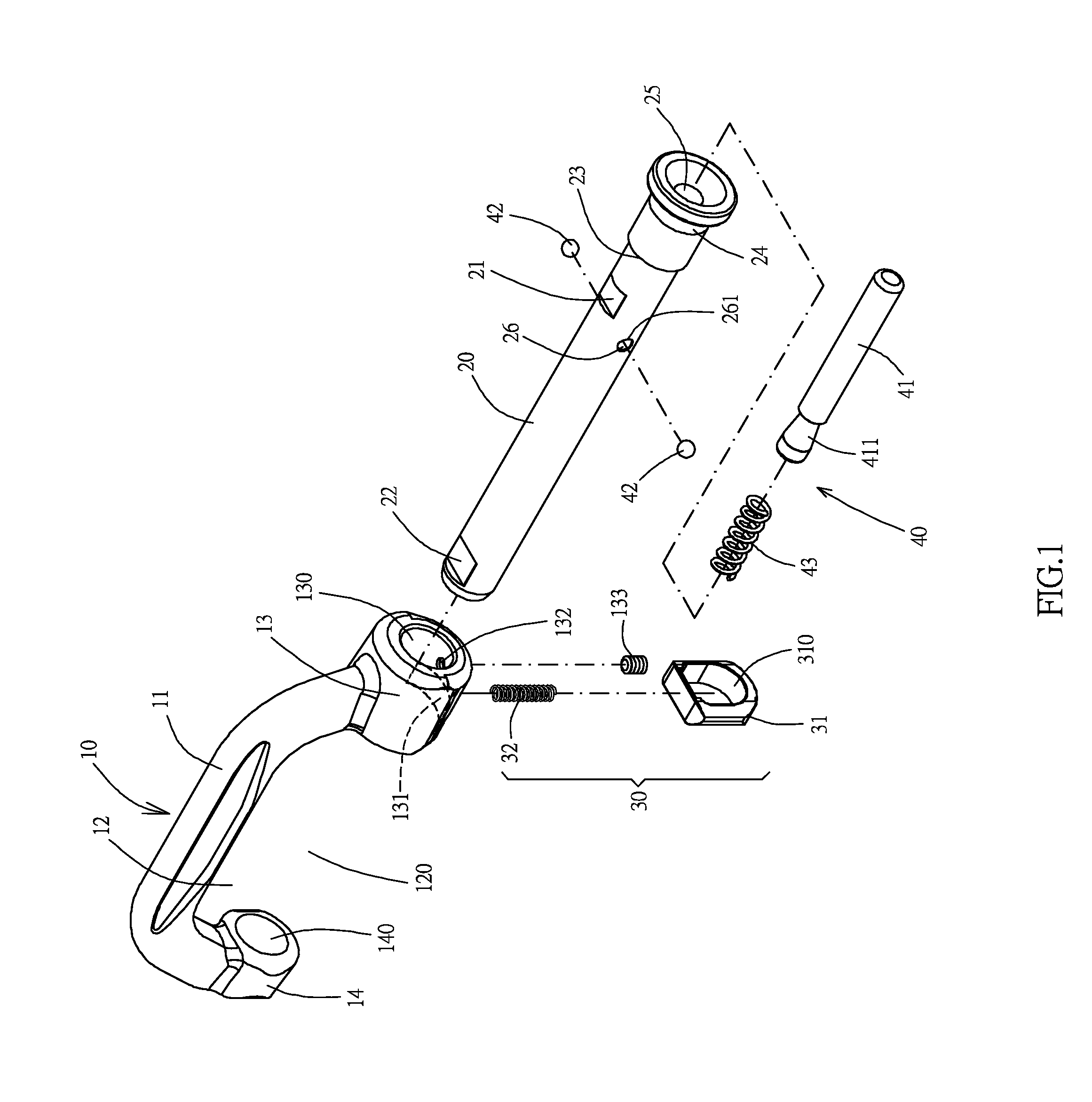
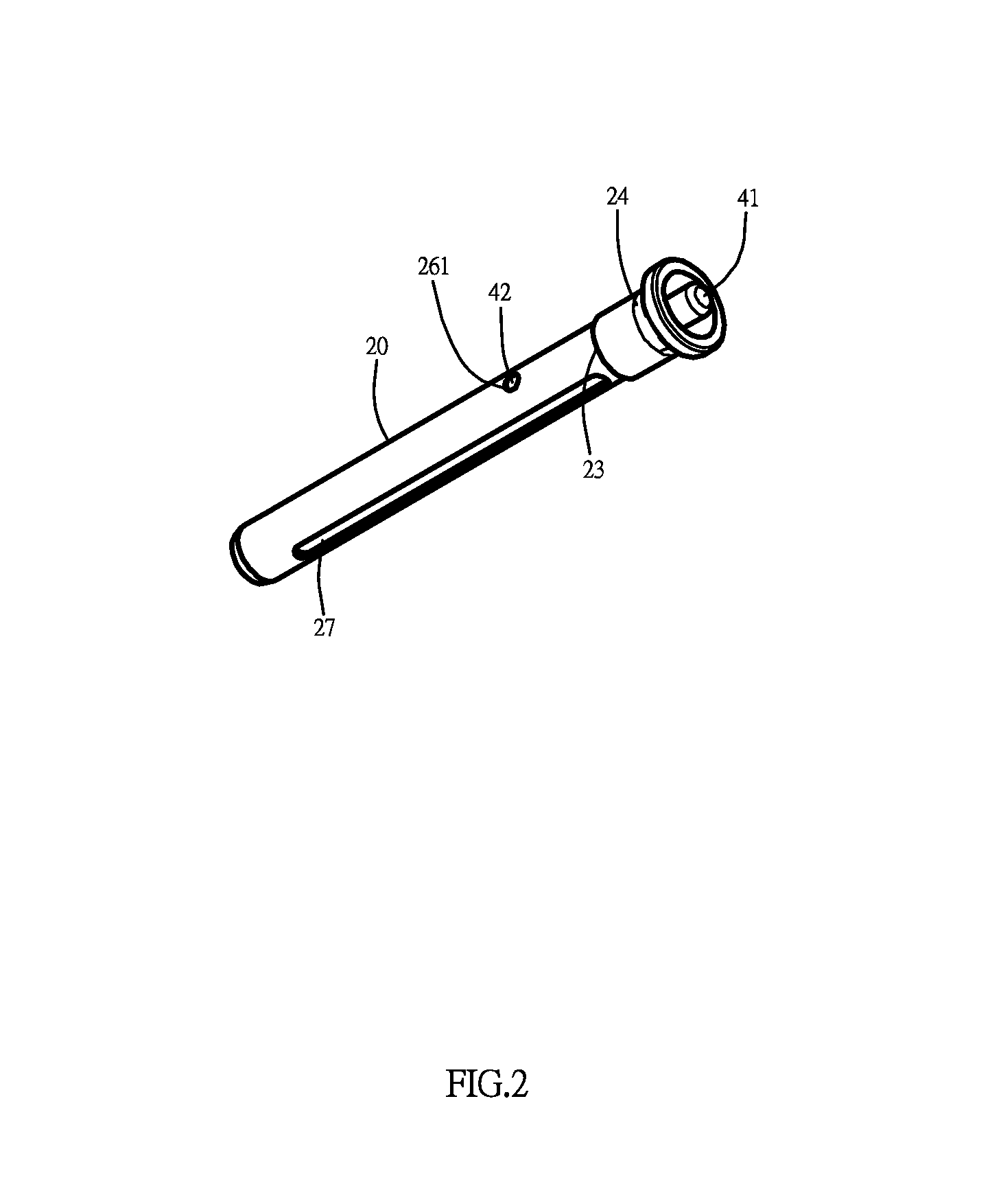
[0027]Please refer to FIGS. 1 to 5, a safety catch connector according to the present invention comprises the following components.

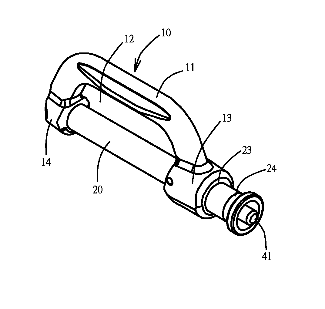
[0028]An elongated catch member 10, having a generally U-shaped configuration, comprises an elongated retention arm 11 thereof to define a hanging space 12 below the retention arm and a notch 120 which forms at the hanging space 12 and faces downward with respect to the retention arm 11. The retention arm 11 has a first sleeve 13 (right sleeve) at one end of the reten...


PUM


Abstract

A safety catch connector includes a catch member, first and second sleeves at two ends of the catch member to define a notch, a locking shaft slidably coupled at the first and second sleeves to selectively open and close the notch, a first controlling unit provided at the first sleeve to releasably lock up the locking shaft at the first sleeve, and a second controlling unit provided at the locking shaft to releasably lock up the locking shaft at the first sleeve, such that the first and second controlling units serves as two safety mechanisms to avoid an unintentional unlocking operation of the locking shaft. The locking shaft is quickly slid to open and close the notch for easy accessing.

Description

NOTICE OF COPYRIGHT[0001]A portion of the disclosure of this patent document contains material which is subject to copyright protection. The copyright owner has no objection to any reproduction by anyone of the patent disclosure, as it appears in the United States Patent and Trademark Office patent files or records, but otherwise reserves all copyright rights whatsoever.BACKGROUND OF THE PRESENT INVENTION[0002]1. Field of Invention[0003]The present invention is a safety equipment, and more particular to a safety catch connector, which can be quickly accessed to couple with a plurality of tools with the safety catch and to separately decouple each tool without accidentally dropping the rest of the tools from the safety catch.[0004]2. Description of Related Arts[0005]Catch devices are widely used in construction sites, chimney and roof repairs, or other operation constructions at height to mitigate the effects of gravity and falling. Accordingly, the catch device comprises a lifting l...

Claims


Application Information

Patent Timeline
Patent Type & Authority Patents(United States)
IPC IPC(8): F16B45/04F16M13/02
CPCF16B45/04F16M13/022A62B35/0075A62B35/0087F16B21/165F16G15/06
Inventor YANG, KAI CHIEHLIN, YI CHING
Owner AKILA TECH CO LTD
Why Eureka
Try Eureka