
Image stabilizing apparatus that corrects image blur caused by hand shake, lens barrel, and optical apparatus

a technology of image stabilization and lens barrel, which is applied in the field of image stabilizing apparatus, can solve the problems of affecting the subsequent drive of the shift member, generating collision noise and an image disturbance, and increasing the size of each part, so as to improve the image stabilization performance and suppress the deterioration of the driving performance of the shi

Active Publication Date: 2016-09-06
CANON KK
View PDF22 Cites 4 Cited by
  • Summary
  • Abstract
  • Description
  • Claims
  • Application Information

AI Technical Summary

Benefits of technology

The present invention describes a device that helps improve image stability while driving. It prevents issues with the shift unit that can affect driving performance.

Problems solved by technology

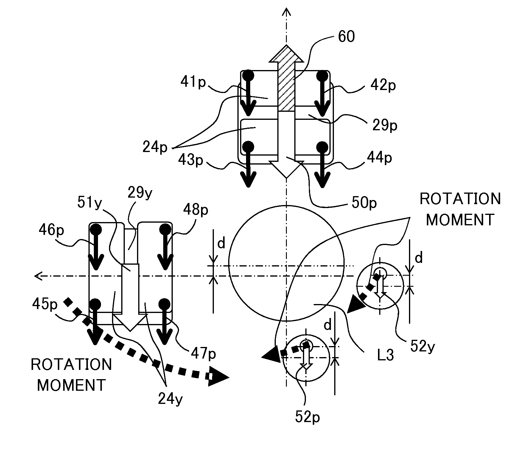
If the shift member contacts a fixed member due to the rotation movement, a collision noise and an image disturbance are generated in some cases.
When parts are damaged by the contact, the subsequent drive of the shift member may be affected.
However, this causes an increase of the size of each part and also leads to an increase of the size of a lens barrel.
Furthermore, if the shift member significantly rotates, characteristics of an output of a position detection sensor change and accurate position detection cannot be performed, and as a result, a so-called crosstalk is generated.
The change of the position detection caused by the rotation leads to an oscillation of a feedback position control in some cases, and it causes a deterioration of an optical performance at the time of the image stabilizing operation.
Additionally, it is difficult to reduce the cost since the number of parts is increased by complicating the configuration of the apparatus.

Method used


Image

  • Image stabilizing apparatus that corrects image blur caused by hand shake, lens barrel, and optical apparatus
  • Image stabilizing apparatus that corrects image blur caused by hand shake, lens barrel, and optical apparatus
  • Image stabilizing apparatus that corrects image blur caused by hand shake, lens barrel, and optical apparatus

Examples


Embodiment Construction

[0023]Exemplary embodiments will be described below with reference to the accompanied drawings. In each of the drawings, the same elements will be denoted by the same reference numerals and the duplicate descriptions thereof will be omitted.

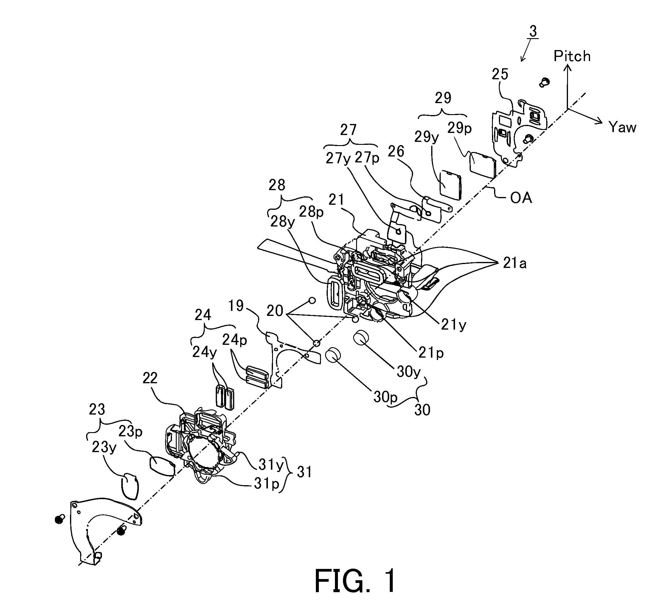
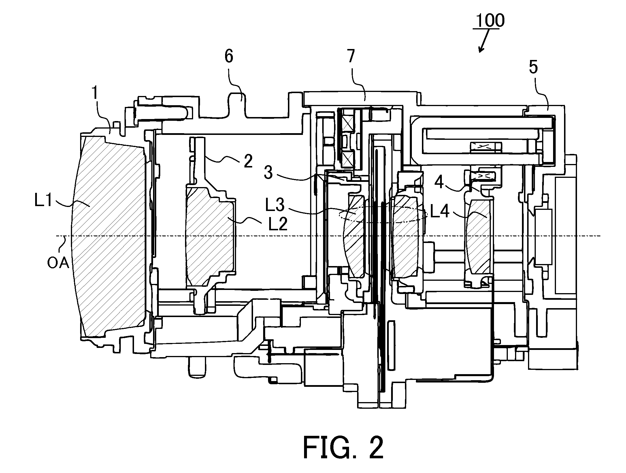
[0024]Referring to FIGS. 2 and 3, a lens barrel that includes a shift unit in an embodiment will be described. FIG. 2 is a cross-sectional view of a lens barrel 100 that includes the shift unit in the present embodiment, and FIG. 3 is an exploded perspective view of the lens barrel 100. The lens barrel 100 of the present embodiment is attached to an image pickup apparatus (an optical apparatus) such as a video camera or a digital still camera or is configured integrally with the image pickup apparatus to be used. The lens barrel 100 is a lens barrel that has a magnification varying optical system of a four-unit configuration of convex, concave, convex, and convex lenses. Reference numeral L1 denotes a first lens unit that is fixed, and reference ...


PUM


Abstract

An image stabilizing apparatus includes a fixed member, a shift member that holds an image stabilizing lens and are movable in a plane orthogonal to an optical axis, a plurality of shift drivers that are disposed at positions different from each other in the plane orthogonal to the optical axis, a gel that is held by one of the shift member and the fixed member, and a protrusion that is provided on the other one of the shift member and the fixed member. Each of the plurality of shift drivers includes a magnet held by one of the shift member and the fixed member, a coil that is held by the other one of the shift member and the fixed member, and a yoke that is held by the other one of the shift member and the fixed member, and a portion of the protrusion is immersed in the gel.

Description

BACKGROUND OF THE INVENTION[0001]1. Field of the Invention[0002]The present invention relates to an image stabilizing apparatus that corrects an image blur caused by hand shake.[0003]2. Description of the Related Art[0004]As one method of correcting a shift of an optical axis that is generated by hand shake at the time of photography to perform an optical image stabilization in a lens barrel of an optical apparatus such as a digital camera, there is a method of performing a shift movement of an image stabilizing lens in a plane orthogonal to the optical axis.[0005]In a shift unit that has two drivers that drive a shift member in a vertical direction (hereinafter, referred to as a “pitch direction”) and in a horizontal direction (hereinafter, referred to as a “yaw direction”) in the plane orthogonal to the optical axis respectively, a change of a position of one of the drivers causes a generation of a pullback force of the other one of the drivers. Japanese Patent Laid-Open No. 2002-...

Claims


Application Information

Patent Timeline
Patent Type & Authority Patents(United States)
IPC IPC(8): G02B27/64H04N5/232H04N5/225
CPCG02B27/646H04N5/2254H04N5/2328H04N23/55H04N23/673H04N23/685
Inventor SATO
Owner CANON KK
Learn More