Explosion-proof braking device with non-magnetic shaft for an explosion-proof electric motor

a technology of braking device and electric motor, which is applied in the direction of electrical equipment, mechanical energy handling, support/enclose/case, etc., can solve the problems of difficult and costly manufacture of explosion-proof self-braking electric motor, inability to carry out maintenance work, and the difficulty of brake manufactur

Active Publication Date: 2016-09-06
COEL MOTORI
View PDF9 Cites 0 Cited by
  • Summary
  • Abstract
  • Description
  • Claims
  • Application Information

AI Technical Summary

Benefits of technology

[0011]It is therefore one object of the present invention to provide an explosion-proof braking device for an explosion-proof electric motor which can solve the above-described problems as well as other problems that will be described below.
[0013]A modular device is thus obtained, which allows to temporarily replace either the brake or the motor independently of each other, thus making for shorter plant downtime and ensuring faster interventions and lower downtime costs.

Problems solved by technology

Consequently, the explosion-proof self-braking electric motor is difficult and costly to manufacture, also because both the motor and the brake, since they are built as one piece, need to be changed depending on the nominal electric and mechanical characteristics required by the specific application.
When installed in plants located in hazardous areas, it is not possible to carry out maintenance work on just one part of a device having a single flame-proof or explosion-proof enclosure, since said enclosure, being a single piece, cannot be opened on site.
The need to ensure the explosion-proof characteristic makes the brake much more difficult to manufacture.

Method used


Image

  • Explosion-proof braking device with non-magnetic shaft for an explosion-proof electric motor
  • Explosion-proof braking device with non-magnetic shaft for an explosion-proof electric motor
  • Explosion-proof braking device with non-magnetic shaft for an explosion-proof electric motor

Examples


Embodiment Construction

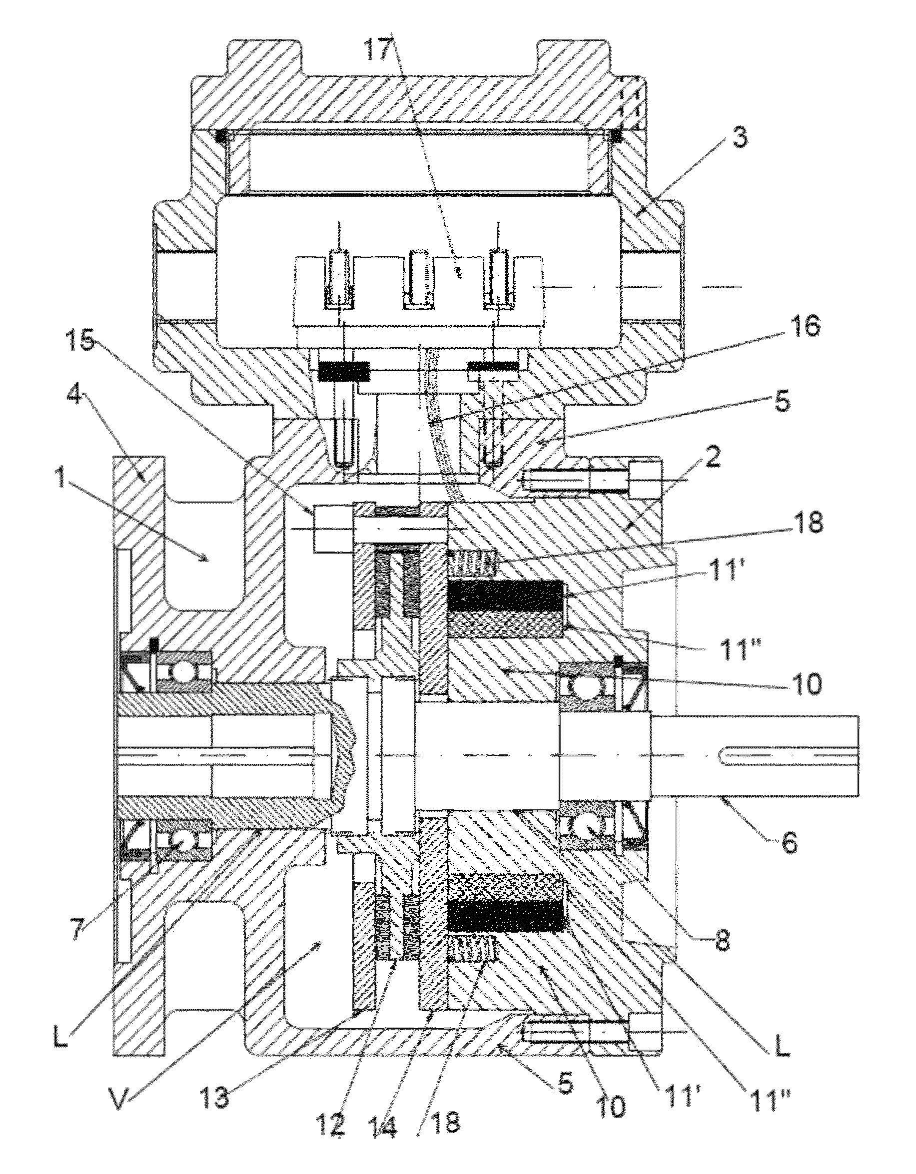
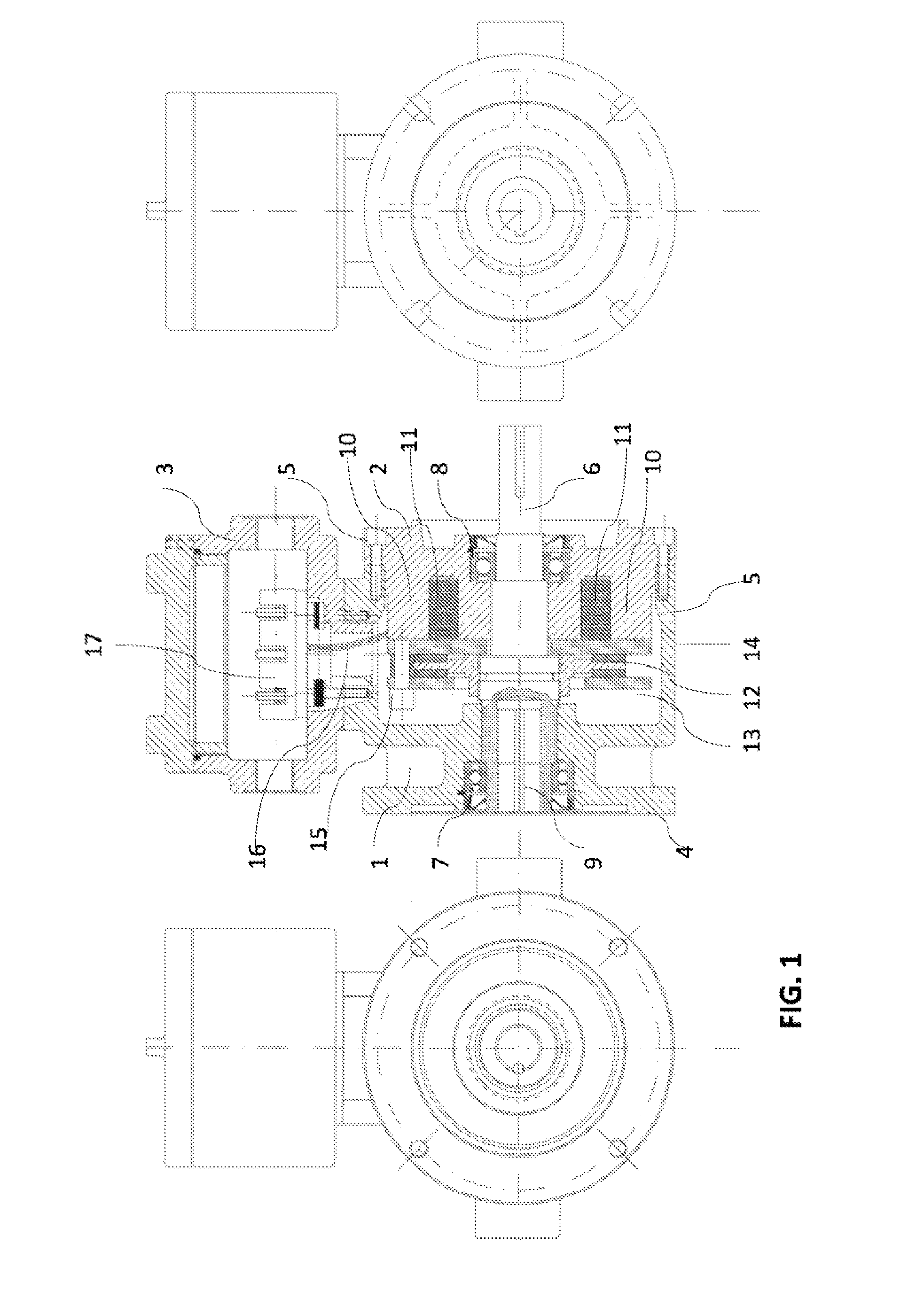
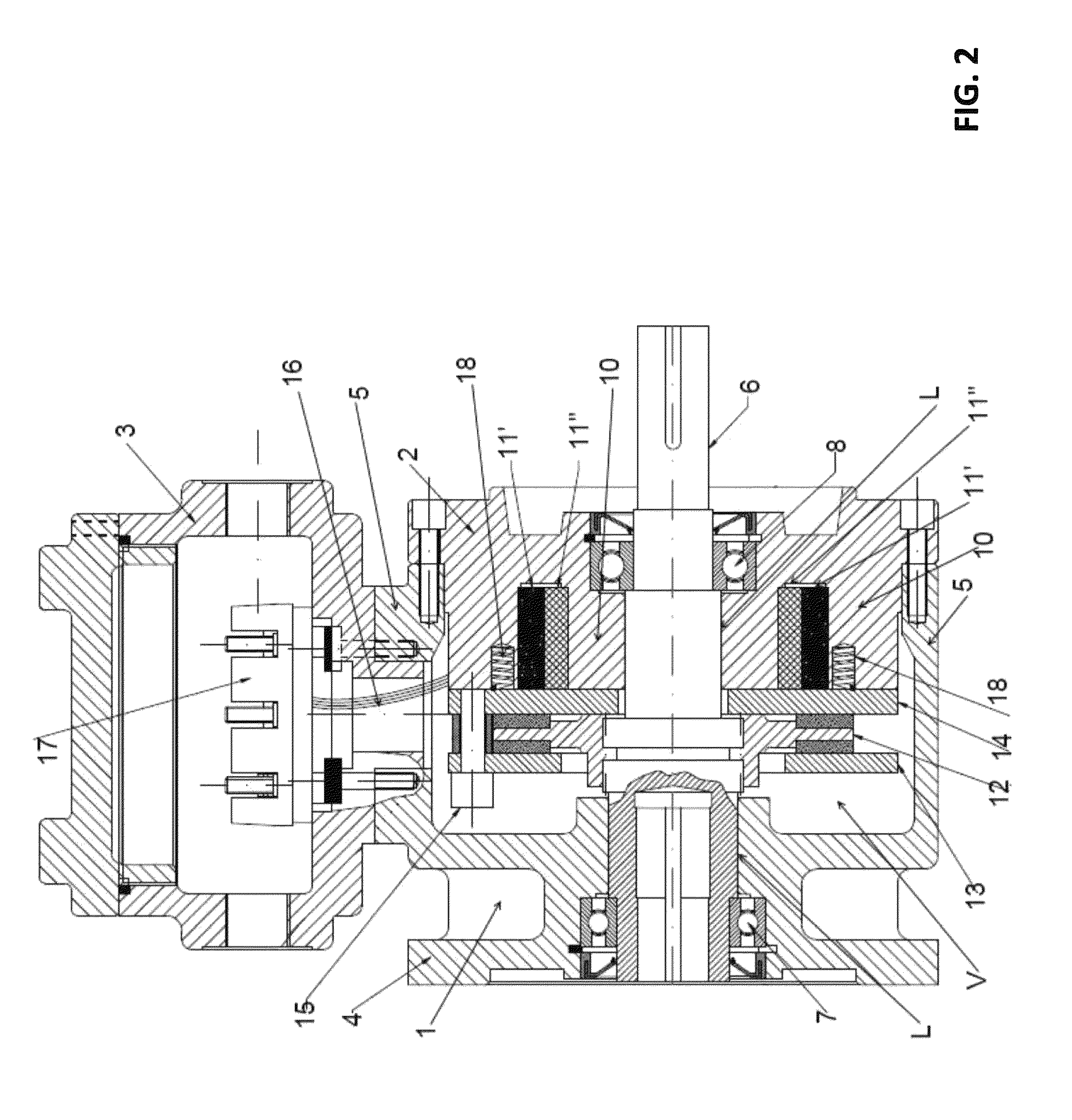
[0022]With reference to the drawings, the following will describe the elements that constitute the explosion-proof braking device according to the invention.

[0023]The enclosure that encloses the device comprises:[0024]a first part 1 (container), internally empty, ending on one side with a flange 4 adapted to be connected to a corresponding flange 4′ of the front part of the motor M, and on the other side ending with an aperture 5;[0025]a second part 2, adapted to be inserted into and fastened to the opening of the first part; as will be described more in detail below, this second part houses the electromagnetic part of the brake and the brake disk;[0026]a third part 3 acting as a terminal box, with the terminals for the electric connection of the brake.

[0027]The three parts are secured to one another by fastening means, e.g., screws.

[0028]A shaft 6, inserted in the enclosure, is adapted to rotate on bearings 7, 8 located at the ends of the enclosure; the end of the shaft facing towa...


PUM


Abstract

An explosion-proof braking device is described, which is configured to be connected to the front flange of an explosion-proof electric motor, the braking device comprising: a shaft (6) connected to the shaft of the motor from the outside, and provided with bearings (7, 8) internal to the device, an electromagnetic brake (11, 12, 13, 14) acting upon said shaft (6), comprising at least one excitation coil (11) and one air gap (10). The shaft (6) is made of a non-magnetic metal alloy, the bearings (7, 8) are so positioned as to lie outside the main flux lines of the magnetic field produced between the coil and the air gap, and the braking device is provided with flame-proof lamination joints of the through or closed type.

Description

CROSS-REFERENCE TO RELATED APPLICATIONS[0001]This application claims the benefit of U.S. Provisional Application No. 61 / 639,272, filed Apr. 27, 2012, which is incorporated herein by specific reference.BACKGROUND OF THE INVENTION[0002]1. Field of the Invention[0003]The present invention relates to the field of explosion-proof electric motors, more specifically to an explosion-proof braking device for an explosion-proof electric motor.[0004]2. Background Art[0005]In the prior art, an explosion-proof self-braking electric motor is equipped with a brake in its rear part which is integral with the structure of the motor as one piece, so as to ensure the desired explosion-proof characteristics.[0006]The known type of explosion-proof self-braking electric motor has a shaft which is integral with an electromagnetic brake disk: when current is supplied to the electromagnet, the brake disk opens and the electric motor is released from the brake; on the contrary, when the electromagnet receive...

Claims


Application Information

Patent Timeline
Patent Type & Authority Patents(United States)
IPC IPC(8): H02K7/10H02K7/102H02K7/104H02K5/136
CPCH02K7/104H02K5/136H02K7/1025
Inventor PAONE, ANDREAPAONE, GUIDO
Owner COEL MOTORI
Why Eureka
Try Eureka