System and method for in-situ state monitoring of a hydraulic system

a hydraulic system and insitu state monitoring technology, applied in the field of systems and methods for insitu state monitoring of hydraulic systems, can solve the problems of time-consuming, difficult to understand the meaning of analysis, and a lot of knowledge of the hydraulic system is required

Inactive Publication Date: 2018-10-30
MERA GMBH
View PDF20 Cites 0 Cited by
  • Summary
  • Abstract
  • Description
  • Claims
  • Application Information

AI Technical Summary

Benefits of technology

[0021]In an embodiment of the monitoring system in accordance with the invention the processor unit is configured for reading out respective actual property values with a sampling rate between once-per-minute and once-per-hour, but preferably with a sample rate of once-per-five-minutes. It will be clear that the advantage of the invention for a large part resides in the in-situ measuring of the properties of the hydraulic fluid. Contrary to taking samples and having them analysed in a laboratory, the monitoring system of the invention renders such handling superfluous. This advantage is imminent at any sampling rate, yet it may be advantageous to have a sampling rate in the order of once-per hour down to once-per five minutes, for example. Such, sampling rate provides for a higher accuracy of the system, and also enables quicker fault detection and thereby allows for quicker intervention in case something is not in order with the hydraulic system.
[0022]In a second aspect the invention relates to a method for in-situ monitoring of a state of a hydraulic system. The method comprises:
[0023]coupling a monitoring system to the hydraulic system such that, in operational use of the monitoring system, hydraulic fluid of the hydraulic system flows from the hydraulic system through a hydraulic circuit of the monitoring system and back to the hydraulic system;
[0024]measuring at least one property of the hydraulic fluid within the hydraulic circuit of the monitoring system;
[0025]determining a condition of the hydraulic fluid running through the hydraulic circuit;
[0026]determining a state of the hydraulic system based upon the condition of the hydraulic fluid, and

Problems solved by technology

The first disadvantage is that it is time consuming, as it will take days to receive the result of the oil analysis from the laboratory.
The second disadvantage is that a lot of knowledge of the hydraulic system is required in order to correctly interpret the meaning of the analysis results in the analysis reports.
Quite often personnel conducting the examination has little knowledge about the meaning of the analysis results, because such interpretation does not form part of the daily operation of the relevant hydraulic oil system.
The third disadvantage is that the taking of oil samples is challenging in terms of repeatability.
This is caused by the high sensitivity of the oil analysis towards contamination.

Method used


Image

  • System and method for in-situ state monitoring of a hydraulic system
  • System and method for in-situ state monitoring of a hydraulic system
  • System and method for in-situ state monitoring of a hydraulic system

Examples


Embodiment Construction

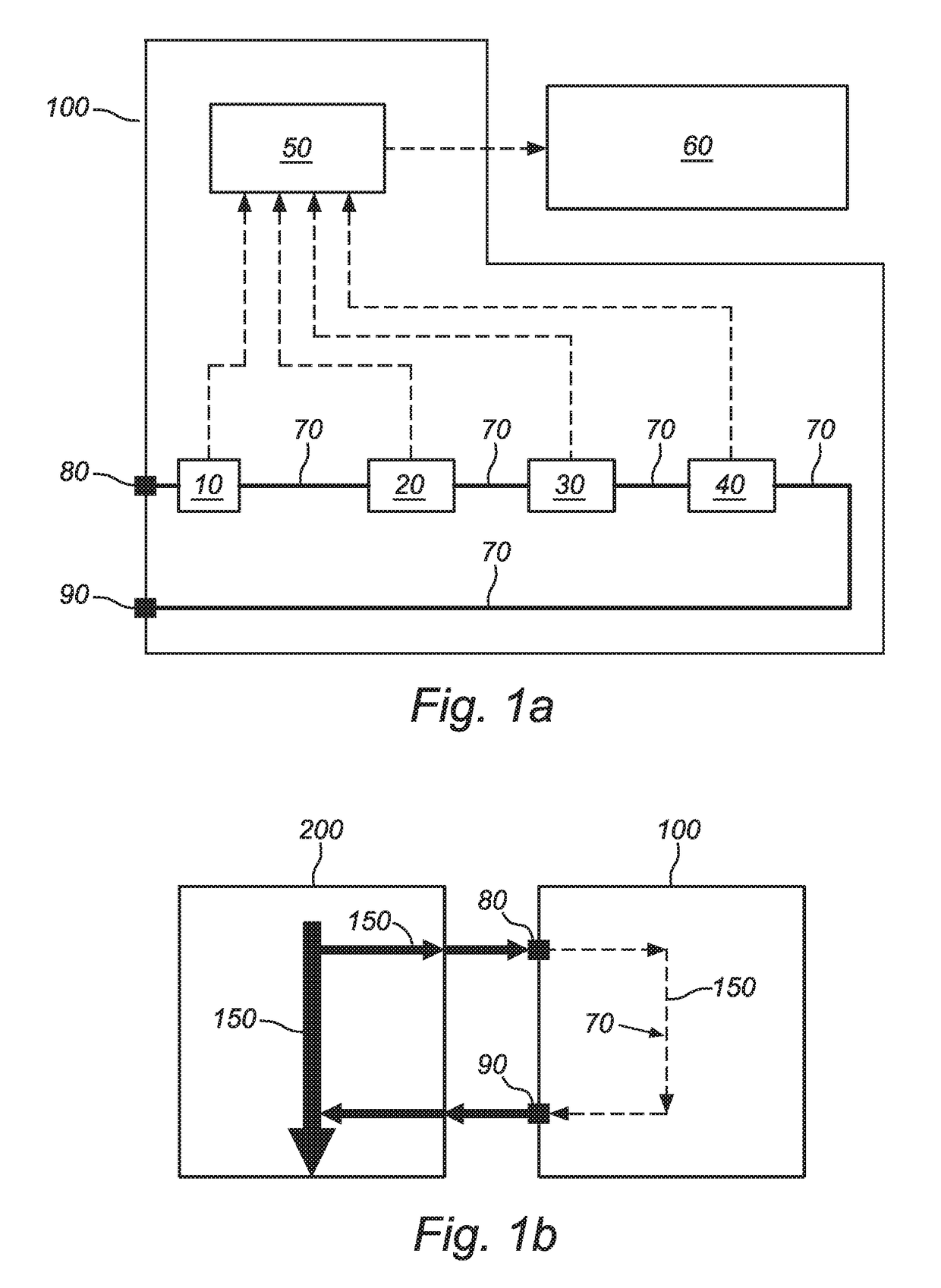
[0045]FIG. 1a shows a schematic view of a monitoring system in accordance with an embodiment of the invention. FIG. 1b shows a schematic view of how the monitoring system 100 is connected to a hydraulic system 200 to be monitored in operational use. The monitoring system 100 comprises a hydraulic inlet 80, a hydraulic outlet 90 and a hydraulic circuit 70 coupled between said inlet 80 and outlet 90. The hydraulic circuit comprises a pump 10 for circulating hydraulic fluid 150 of the hydraulic system 200 through the hydraulic circuit 70 of the monitoring system 100. Within the hydraulic circuit 70 there is further provided three sensor units 20,30,40, which each measure at least one of the earlier discussed properties of the hydraulic fluid 150, namely temperature, viscosity, dielectric permittivity, relative humidity, electrical conductivity, and particle size distribution. In an embodiment the first sensor unit 20 measures temperature and viscosity, the second sensor unit 30 measure...


PUM

PropertyMeasurementUnit
temperatureaaaaaaaaaa
viscosityaaaaaaaaaa

Abstract

A monitoring system is for in-situ monitoring of a state of a hydraulic system. A hydraulic fluid inlet is coupled to the hydraulic system. A hydraulic fluid outlet is coupled to the hydraulic system. A hydraulic circuit is between the inlet and the outlet. A sensor unit is in the hydraulic circuit. The sensor unit is configured for measuring at least one property of the hydraulic fluid within the hydraulic circuit in operational use of the monitoring system. A processor unit reads out at least one output of the at least one sensor unit and determines a condition of the hydraulic fluid running through the hydraulic circuit. The processor unit determines a representative of a state of the hydraulic system based upon the condition of the hydraulic fluid and is coupled to a display device for displaying the representative.

Description

CROSS-REFERENCE TO RELATED APPLICATIONS[0001]This application is the U.S. national stage application of International Application PCT / NO2015 / 050065, filed Apr. 9, 2015, which international application was published on Oct. 15, 2015, as International Publication WO 2015 / 156681 in the English language. The International Application claims priority of Norwegian Patent Application No. 20140477, filed Apr. 11, 2014. The international application and Norwegian application are both incorporated herein by reference, in entirety.FIELD OF THE INVENTION[0002]The invention relates to a monitoring system for in-situ monitoring of a state of a hydraulic system. The invention further relates to a method for in-situ monitoring of a state of a hydraulic system.BACKGROUND OF THE INVENTION[0003]Different methods of monitoring the condition of hydraulic systems have been reported. Condition monitoring of hydraulic oil systems is possible by several methods. Among them are techniques such as visual insp...

Claims


Application Information

Patent Timeline
Patent Type & Authority Patents(United States)
IPC IPC(8): G06F19/00G01N33/28F15B21/04F15B19/00G08B21/18F15B21/045
CPCF15B19/005F15B21/045G01N33/28G08B21/182F15B2211/857F15B2211/6303F15B2211/6343F15B21/04G06F15/00
Inventor IVERSEN, ERLINGFRONSDAL, DENNIS
Owner MERA GMBH
Why Eureka
Try Eureka