Assembling flanged couplings

a technology of flanged couplings and couplings, which is applied in the direction of flanged joints, pipe laying and repair, mechanical equipment, etc., can solve the problems of shortening the ‘weather window, difficult and long operation of aligning and pulling together two flanges for couplings, and magnifying the difficulty of performing these operations, so as to facilitate remote intervention, facilitate operation, and facilitate handling

Active Publication Date: 2022-06-21
SUBSEA 7 GESTAO BRASIL SA
View PDF13 Cites 0 Cited by
  • Summary
  • Abstract
  • Description
  • Claims
  • Application Information

AI Technical Summary

Benefits of technology

[0041]The invention solves problems encountered when aligning flanges during connection, overcoming misalignment of termination face planes of the flanges. The invention facilitates remote intervention, combining safety of operation with easier handling and faster intervention than was previously possible. Thus, the invention provides a safer, simpler and quicker way of aligning flanges than current, largely manual techniques.
[0042]With just one type of tool, the invention can solve problems of flange approximation and assembly for all flanges used commercially in the oil and gas industry. The tool is ideally adapted for offshore use. The invention enables hydraulic intervention to be applied simply from a single source through a valve manifold that controls a sequence of pressure application. The necessary intervention may be applied largely outside the line-of-fire of stress loading in the flanged parts, allowing safer operation with less risk to personnel and equipment in the event of mechanical failure.

Problems solved by technology

The challenges of performing these operations are magnified where assembly is performed underwater or by remote control, for example using an unmanned underwater vehicle (UUV) such as an ROV.
Aligning and pulling together two flanges for coupling can be a difficult and lengthy operation due to variable 3D geometry and mechanical stresses arising from deformation of the parts, such as pipes, that carry the flanges.
It also shortens the ‘weather window’ of favourable sea conditions that may be required.
In these circumstances, personnel working in close proximity may be exposed to components that are under considerable stress.
This is risky due to the elastic energy that will be stored in the components when large forces are applied to align the flanges, especially if the flanges have misaligned mating faces.
This presents a serious risk of injury to personnel, in addition to the risk of damage to equipment and assets even if personnel can be kept at a safe distance by the use of automation.
This has the drawback that connection and disconnection of the wires requires direct intervention on the flanges.
Also, the wires are vulnerable to break if they encounter sharp edges.
For example, a subsea alignment jacking system is described in the Applicant's International patent application published as WO 03 / 040602. FIG. 4 of WO 03 / 040602 shows that the system is bulky and complex.
A drawback of all jacks is their limited stroke or range of action.
That initial phase can be complex to manage, especially when rotation is also needed to bring the flanges into substantially parallel planes.
A key drawback of this solution is the need for swiveling connectors, which are expensive and tend to lower the reliability of a pipeline that incorporates them.
However, that system is designed for aligning connector hubs and is not capable of aligning flanges; this is because rotation around the axial axis may be needed to align the bores of the flanges for bolting.
Known flange pulling systems also have drawbacks.
If the link is a wire rope or cable, it may be damaged by the edges of the holes if misalignment is excessive; consequently, the system remains sensitive to misalignment of the flanges in transverse planes.
Otherwise, the rod or bar or the flanges may become bent or otherwise damaged.

Method used


Image

  • Assembling flanged couplings
  • Assembling flanged couplings
  • Assembling flanged couplings

Examples


Embodiment Construction

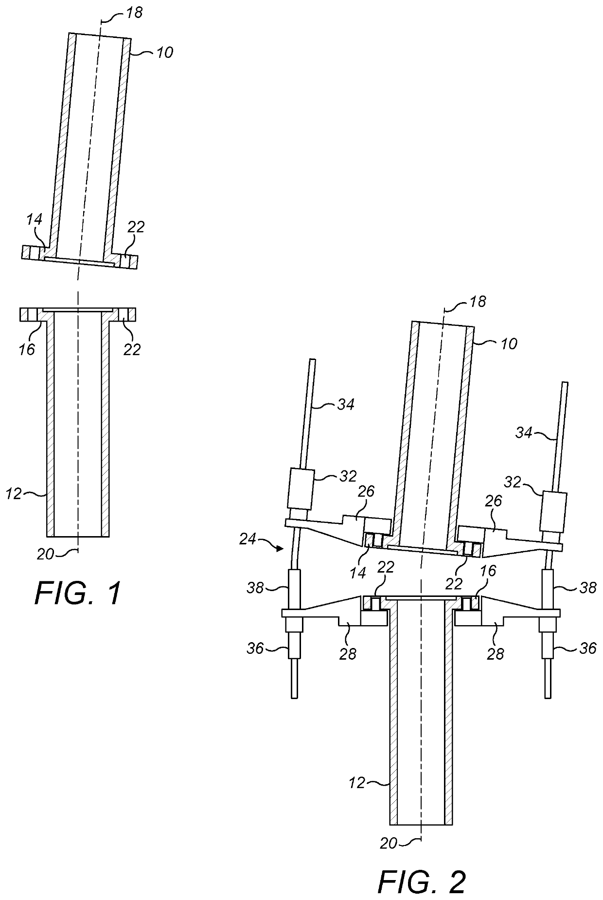
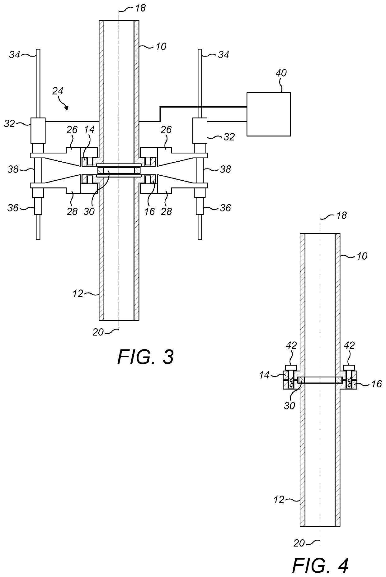
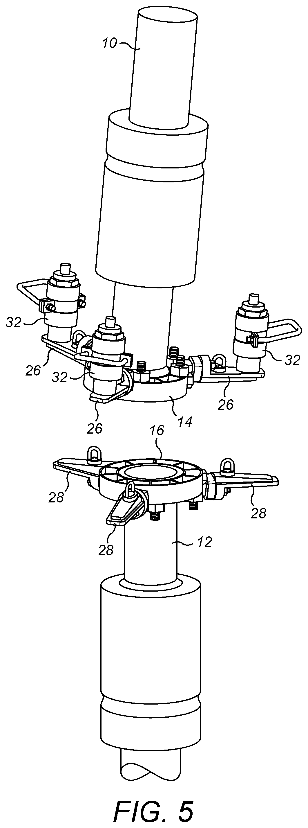
[0057]FIGS. 1 to 4 are simplified schematic drawings that show the principle of the invention. Conversely, FIGS. 5 to 13, which will be described later, are detailed drawings of a preferred embodiment of the invention that embodies the principle shown in FIGS. 1 to 4.

[0058]FIG. 1 shows upper and lower pipes 10, 12, spaced apart and mutually misaligned but facing each other end-to-end. In this example, the pipes 10, 12 are subsea pipes located underwater although they could instead be above the surface, for example on an installation vessel, or on land.

[0059]It will be appreciated that references to ‘upper’ and ‘lower’ in this description are merely for convenience of illustration and explanation. In reality, pipes that require end-to-end coupling may be in a variety of orientations other than approximately vertical, upright orientation shown in the example here.

[0060]Each pipe 10, 12 terminates in a respective flange 14, 16 whereby the pipes 10, 12 can be coupled together for fluid ...


PUM


Abstract

A pulling and alignment system for flanged components has pairs of flange attachments fixed to respective flanges of components that are to be pulled together and aligned for coupling. A puller device is supported by a flange attachment of each pair. A flexible elongate pulling link extends between the flange attachments of the pair and is engaged by, and movable relative to, the puller device to act in tension between those flange attachments. Each flange attachment is a flange extension that comprises an arm cantilevered from a mounting to extend beyond the flange and to hold the pulling link outboard of the flange. The pulling link is an articulated rod having a longitudinal series of rigid elements, each of those elements being pivotably coupled to at least one other of those elements.

Description

BACKGROUND OF THE INVENTION[0001]This invention relates to the assembly of flanged couplings or joints between separate parts, such as lengths of pipe to be joined end-to-end.[0002]Flanged couplings are widely used in the offshore oil and gas industry to connect subsea equipment, spools, structures and rigid or flexible pipelines for various applications. Specific examples of flanged coupling applications are: pipe-to-pipe connections in trenches, normally involving flexible pipelines; connections between flexible pipelines and items of subsea equipment such as pipeline accessories; and connections between items of subsea equipment and spool pipes that carry fluids to or from the subsea equipment.[0003]A pipe flange comprises a radially-extending disc, collar or ring around a central hub that is screwed or welded to a pipe end. A series of parallel holes extends through the flange disc to receive fastenings such as bolts. A sealing gasket may be inserted between mating faces of oppo...

Claims


Application Information

Patent Timeline
Patent Type & Authority Patents(United States)
IPC IPC(8): F16L1/09F16L23/02F16L23/00F16L1/10F16L1/26
CPCF16L23/003F16L1/10F16L23/02F16L1/26F16L23/036B23P19/10F16L1/09F16L1/20F16L1/235
Inventor DE LEMOS JUNIOR, LUIZ CARLOS
Owner SUBSEA 7 GESTAO BRASIL SA
Why Eureka
Try Eureka