
Method for detecting the condition of a lamp for heating blank bodies made of thermoplastic material and heating installation arranged for use thereof

a technology of thermoplastic material and lamp body, which is applied in the field of container manufacturing, can solve the problems of ineffective detection of envelope breaking, time-lapse, and envelope disintegration, and achieve the effect of accurate signalling and low cos

Inactive Publication Date: 2011-06-14
SIDEL PARTICIPATIONS SAS
View PDF9 Cites 0 Cited by
  • Summary
  • Abstract
  • Description
  • Claims
  • Application Information

AI Technical Summary

Benefits of technology

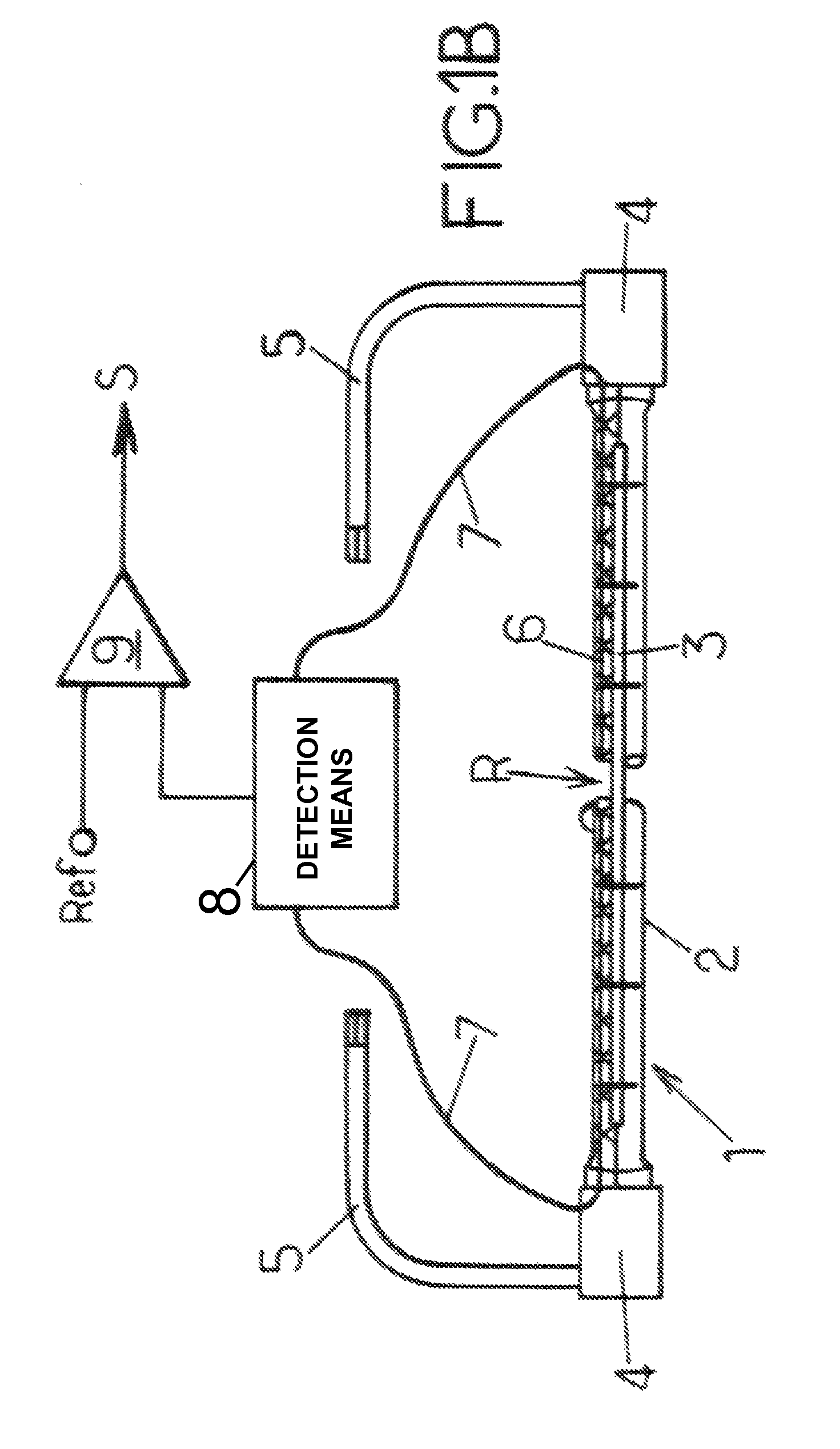
[0009]The essential purpose of the invention is to provide means (method and installation) which are adapted for detecting the breaking of the envelope as soon as this occurs and while the filament itself can still be intact, so that measures can promptly be taken to avoid serious consequences to the operation of the heating installation and / or injury to the machine-operator and maintenance staff.
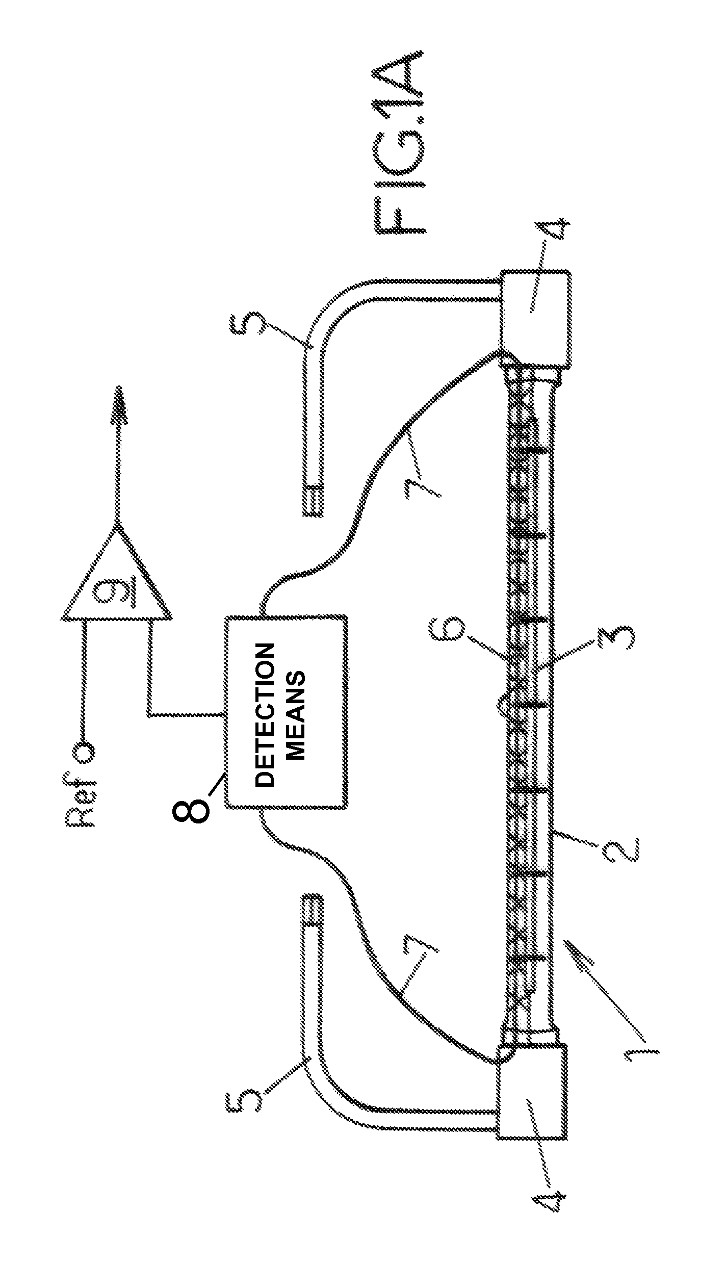
[0013]A simple embodiment of the provisions of the invention can consist in that several heating lamps are provided, each equipped with a conductive element which is mechanically integral with its own envelope, in that all the components are electrically independent of one another, and in that detection of said electrical variable is carried out on each conductive element of each lamp. In other words, in this case each lamp is monitored individually and an alarm can signal precisely the lamp involved, when an incident occurs. Such an embodiment offers the advantage of accuracy and therefore of rapid intervention to replace the defective lamp and return the installation to operation; however it requires a relatively large quantity of equipment which, taken overall, is expensive to purchase, install and maintain.
[0014]Therefore, another embodiment can also be provided which is simpler and less expensive, which consists in that several heating lamps are provided, each equipped with a conductive element which is mechanically integral with its own envelope, in that several conductive elements belonging to the respective lamps of a group of lamps are electrically connected in series to each other and in that the detection of said electrical variable is carried out between the terminals of the set of conductive elements in series of said group of lamps. In the event of the envelope of a lamp breaking, the alarm is then given for a group of lamps in which the lamp involved is included, and then the maintenance staff are responsible for determining which lamp of said group must actually be dealt with.
[0023]A first solution can consist in that the installation comprises several lamps provided with respective conductive elements and in that individual detection means are operationally associated with said respective conductive elements of the lamps. In other words, the installation is arranged in such a way that each lamp is monitored individually and accurately signalled when breakdown occurs.
[0024]However, a more economical solution can consist in that the installation comprises several lamps provided with respective conductive elements, in that several conductive elements belonging to the respective lamps of a group of lamps are electrically connected to each other in series and in that said detection means are connected to the terminals of the conductive elements in series, as a whole, of said group of lamps. Signalling a detected defect is then carried out by a group of lamps and no longer individually per lamp, but the equipment used for this purpose is simpler, and therefore the cost is lower.

Problems solved by technology

If the operating temperature is too high (in the case of insufficient ventilation) or too low (in the case of excessive ventilation), elimination of the tungsten particles by the halogen does not take place, or takes place insufficiently, and tungsten is deposited on the envelope, particularly made of glass or quartz: the envelope then finally disintegrates and breaks.
It has however been noted that breaking of the envelope is not necessarily accompanied by the concomitant breaking of the lamp filament, and there can be a consequent time-lapse (for example several seconds, even several tens of seconds) before the filament breaks (breaking caused by the filament coming into contact with the oxygen in the surrounding air, and its rapid oxidation).
For that reason, the usual means employed to detect breaking of the filament are ineffective for detecting the breaking of the envelope which may precede the breaking of the filament.
Now, breaking the envelope of a lamp is a far from harmless event, and can result in significant damage: the fragments of the envelope, particularly glass or quartz, can destroy adjacent lamps; they can damage the blanks moving past and render them unsuitable for commercial use; they can even lodge in one of these and subsequently remain there, even in the final container; they can damage mechanical parts of the installation and cause jamming in the installation operating at considerable speeds.
In all cases, an emergency shutdown of the installation is required, resulting in a loss of production.
Finally, the debris of the envelope can cause injury to the staff responsible for repairing the installation.
The current means, the implementation of which is essentially based on the physical condition of the lamp filament, do not make it possible to detect the breaking of the envelope alone, while the filament is still intact.

Method used


Image

  • Method for detecting the condition of a lamp for heating blank bodies made of thermoplastic material and heating installation arranged for use thereof
  • Method for detecting the condition of a lamp for heating blank bodies made of thermoplastic material and heating installation arranged for use thereof
  • Method for detecting the condition of a lamp for heating blank bodies made of thermoplastic material and heating installation arranged for use thereof

Examples


Embodiment Construction

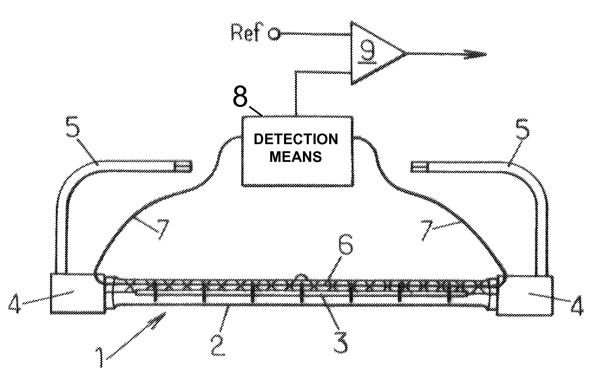
[0028]Reference will now be made to FIGS. 1A and 1B, and more particularly firstly to FIG. 1A. The invention is situated in the context of an installation for heating the blank bodies made of thermoplastic material, intended for the manufacture by blow moulding or stretch-blow moulding of containers such as bottles, flasks or others. A heating installation of this type comprises a multiplicity of incandescent heating lamps, in general of the halogen atmosphere type, adapted for emitting an infrared electromagnetic radiation of given temperature and colour. These lamps, generally tube-shaped, are arranged parallel to each other in columns and distributed in several successive columns, for example unilaterally on one side of the path followed by the blank bodies driven by a conveyor.

[0029]In FIG. 1A, the part of this heating installation useful in order to assist understanding of the invention is shown in a very diagrammatic representation, namely a lamp 1 (here represented in its sta...


PUM

PropertyMeasurementUnit
electrically conductiveaaaaaaaaaa
electrical resistanceaaaaaaaaaa
conductiveaaaaaaaaaa

Abstract

The condition of a lamp (1) for heating blank bodies made of thermoplastic material, intended for the manufacture of containers by blow moulding or stretch-blow moulding, is detected. The infrared electromagnetic radiation lamp has an envelope (2) made of glass or quartz enclosing a filament (3); the lamp is provided with an electrically conductive element (6) mechanically integral with the envelope; the conductive element is made electrically live and an electrical variable is continuously detected between the terminals of the conductive element when the lamp is in operation; and data representative of the condition of the conductive element, and of the envelope, is supplied.

Description

FIELD OF THE INVENTION[0001]The present invention relates generally to the field of the manufacture of containers made from thermoplastic material by blow moulding or stretch-blow moulding of hot blanks (preforms or intermediate containers), and it relates more particularly to improvements to the installations for heating the blanks prior to the blow moulding or stretch-blow moulding stage.BACKGROUND OF THE INVENTION[0002]The blanks are heated by subjecting their bodies to an infrared electromagnetic radiation of appropriate wavelength emitted by infrared incandescent lamps, typically in the general shape of a tube. In practice, the blanks are moved by a conveyor such that their bodies follow a determined path, along which heating lamps are arranged in numbers and positions adapted to the thermal effect to be generated within the thermoplastic material.[0003]It is known to monitor the condition, operational or no operational, of the lamps by using various electrical solutions, the m...

Claims


Application Information

Patent Timeline
Patent Type & Authority Patents(United States)
IPC IPC(8): G01R31/08G01R31/00
CPCH05B3/0057B29C49/64B29C2035/0822G01R31/44B29C2037/90
Inventor FEUILLOLEY, GUY
Owner SIDEL PARTICIPATIONS SAS
Learn More