
Mobile bearing glenoid prosthesis

a glenoid and mobile technology, applied in the field of shoulder prostheses, can solve the problems of limiting the range of motion affecting the quality of the patient's shoulder joint,

Active Publication Date: 2016-09-13
DEPUY SYNTHES PROD INC
View PDF18 Cites 1 Cited by
  • Summary
  • Abstract
  • Description
  • Claims
  • Application Information

AI Technical Summary

Benefits of technology

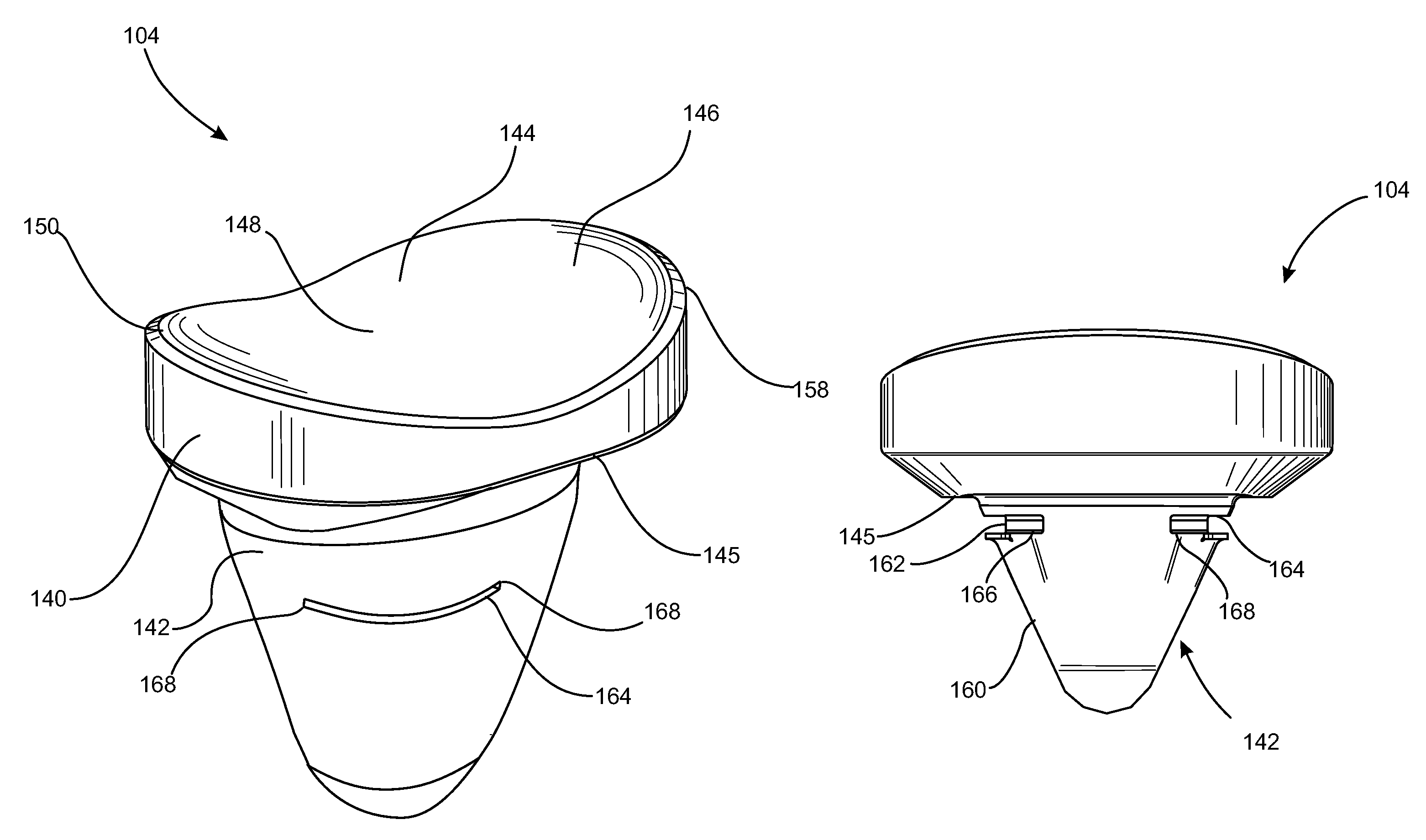
The present patent provides a prosthesis assembly for use with a scapula that includes a spherical humeral component and a stretched glenoid bearing. The glenoid bearing has a unique design with a first rim portion, second rim portion, and a pair of spaced apart third rim portions that define a non-circular shape when projected onto a plane. The assembly also includes a base component and a glenoid bearing component that are rotatably coupled together to allow for limited movement of the glenoid bearing component relative to the base component. The unique design of the glenoid bearing and the rotationally coupled components provide improved stability and reduced wear of the prosthesis assembly.

Problems solved by technology

During the lifetime of a patient, the glenoid fossa 14 may become worn, especially at its posterior and / or superior portions thereby causing severe shoulder pain and limiting the range of motion of the patient's shoulder joint.
Accordingly, the translation of the humeral head in the shoulder joint after arthroplasty can result in edge loading of the prosthesis assembly.
Edge loading can result in limited motion, instability, and accelerated wear.
This approach accommodates translation of the humeral head but does not eliminate edge loading.
Additionally, the resulting loss of optimal coverage of the humeral head results in increased instability.
This approach also fails to eliminate edge loading and further results in reduced stability.

Method used


Image

  • Mobile bearing glenoid prosthesis
  • Mobile bearing glenoid prosthesis
  • Mobile bearing glenoid prosthesis

Examples


Embodiment Construction

[0028]While the shoulder prosthesis assembly described herein is susceptible to various modifications and alternative forms, specific embodiments thereof have been shown by way of example in the drawings and will herein be described in detail. It should be understood, however, that there is no intent to limit the shoulder prosthesis assembly to the particular forms disclosed, but on the contrary, the intention is to cover all modifications, equivalents, and alternatives falling within the spirit and scope of the invention as defined by the appended claims.

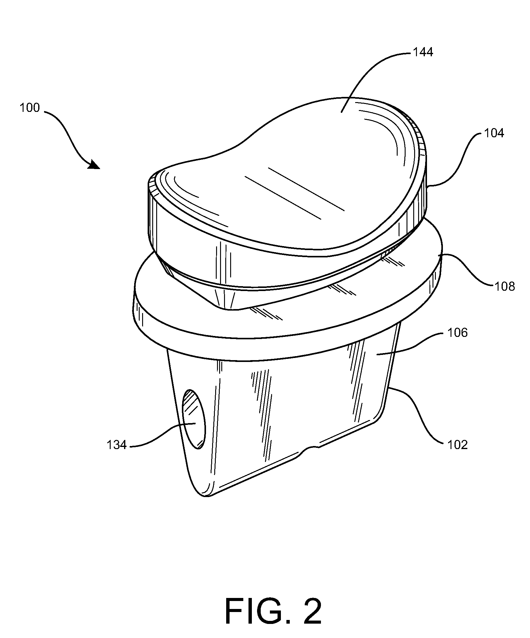
[0029]Referring now to FIG. 2, there is shown a shoulder prosthesis assembly 100 that is configured to be implanted in a human scapula. The prosthesis assembly 100 includes a glenoid base component 102 and a glenoid bearing 104. The glenoid base component 102 in this embodiment is made entirely of a metallic material, while the glenoid bearing 104 is made entirely of a polymeric material. Preferably, the glenoid base component 102 ...


PUM


Abstract

A method of installing a prosthesis assembly includes installing a base component in a prepared glenoid vault, axially aligning a plurality of slots in one of a stretched glenoid bearing component and a base component with a plurality of ridges in the other of the glenoid bearing component and the base component, each of the plurality of slots having a maximum length which is greater than a maximum length of a respective one of the plurality of ridges, engaging each of the plurality of ridges with the respective one of the plurality of grooves thereby rotatably coupling the glenoid bearing component and the base component and limiting axial movement of the glenoid bearing component relative to the base component, and placing the bearing surface into articulating contact with a humeral head.

Description

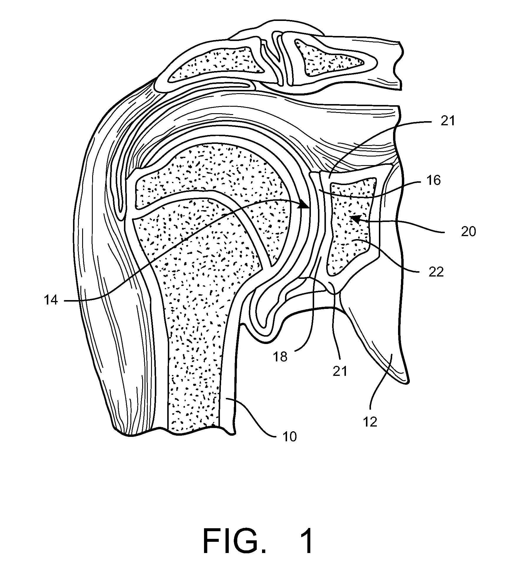
[0001]This application is a utility application claiming priority to U.S. patent application Ser. No. 13 / 094,180, filed Apr. 26, 2011, entitled “Mobile Bearing Glenoid Prosthesis” (now U.S. Pat. No. 8,882,845, issued Nov. 11, 2014), which in turn claims priority to U.S. Provisional Application No. 61 / 331,458, filed May 5, 2010, entitled “Mobile Bearing Glenoid Prosthesis,” the disclosures of which are both incorporated by reference herein in their entirety.BACKGROUND[0002]The present disclosure relates generally to shoulder prostheses, and more particularly to shoulder prostheses configured for use in shoulders having glenoid vault erosion or defects.[0003]A typical shoulder or glenohumeral joint is formed in a human body where the humerus 10 movably contacts the scapula 12 as shown in FIG. 1. The scapula 12 includes a glenoid fossa 14 that forms a socket against which the head of the humerus 10 articulates. At this socket, the scapula 12 includes cartilage 16 that facilitates such ...

Claims


Application Information

Patent Timeline
Patent Type & Authority Patents(United States)
IPC IPC(8): A61F2/40A61F2/30
CPCA61F2/4081A61F2002/305A61F2002/30125A61F2002/30332A61F2002/30364A61F2002/30934A61F2220/0025A61F2220/0033A61F2230/0008
Inventor WIRTH, MICHAEL A.IANNOTTI, JOSEPH P.WILLIAMS, JR., GERALD R.LAPPIN, KYLE E.STONE, MATTHEW T.
Owner DEPUY SYNTHES PROD INC
Learn More