Wire tensioner tip for use with wire fixation bolt

a wire fixation bolt and wire tensioner technology, applied in the field of wire tensioners, can solve the problems of preventing the wire from being properly tensioned, affecting the operation, and affecting the operation, and causing injury to the surgeon, the patient, or both

Active Publication Date: 2016-09-20
TEXAS SCOTTISH RITE HOSPITAL FOR CHILDREN
View PDF27 Cites 4 Cited by
  • Summary
  • Abstract
  • Description
  • Claims
  • Application Information

AI Technical Summary

Benefits of technology

[0009]The wire fixation system may further comprise a wire tensioning tip operable to engage with the second wire fixation bolt and with a wire tensioning device. The wire tensioning tip may further comprise a shaped head recess portion operable to engage with the shaped head of the wire fixation bolt, a body shoulder portion distal to the shaped head recess portion and operable to engage with the first body of the wire fixation bolt, and a shoulder recess portion distal to the body shoulder portion and operable to engage with the shoulder of the wire fixation bolt. The wire tensioning tip is operable to stabilize the head portion of the second wire fixation bolt and prevent the second wire fixation bolt from rotating when the wire tensioning tip is received onto the wire and engaged with the shaped head of the second wire fixation bolt.

Problems solved by technology

However, before the wire may be fixed across the fixation rings by the nuts and bolts, the wire must be tensioned to an optimal tension, which is a difficult, complicated, and overly wieldy procedure.
If the wires are not oriented orthogonally to the outer surface of the fixation ring, the tensioner may slip under heavy loads, preventing the wires from being properly tensioned and possibly injuring the surgeon, the patient, or both.

Method used


Image

  • Wire tensioner tip for use with wire fixation bolt
  • Wire tensioner tip for use with wire fixation bolt
  • Wire tensioner tip for use with wire fixation bolt

Examples


Embodiment Construction

[0025]In the embodiments described below, various components may be defined in relation to each other using the positional terms of superior / inferior, medial / lateral, and distal / proximal. In operation and while used during surgery, “proximal” refers to closer to the user / surgeon, while “distal” refers to away from the user / surgeon and closer to the subject / patient.

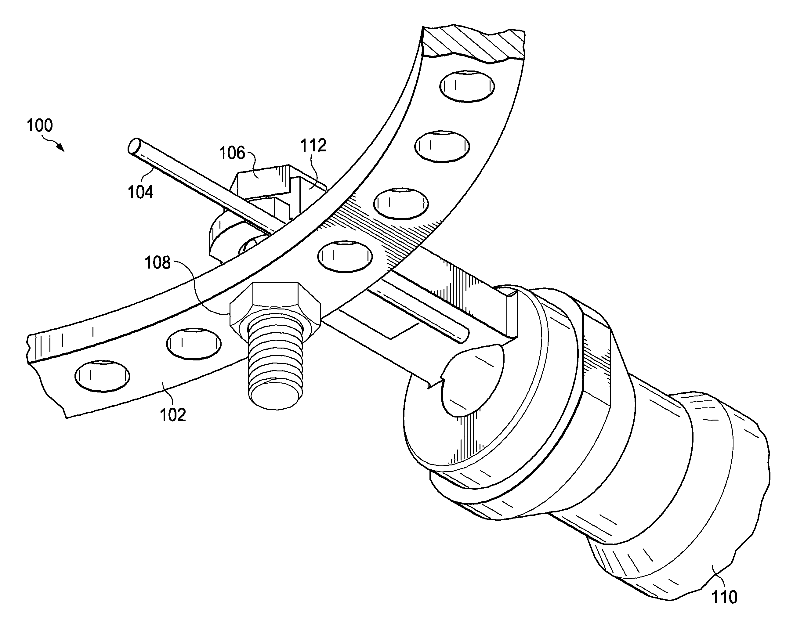
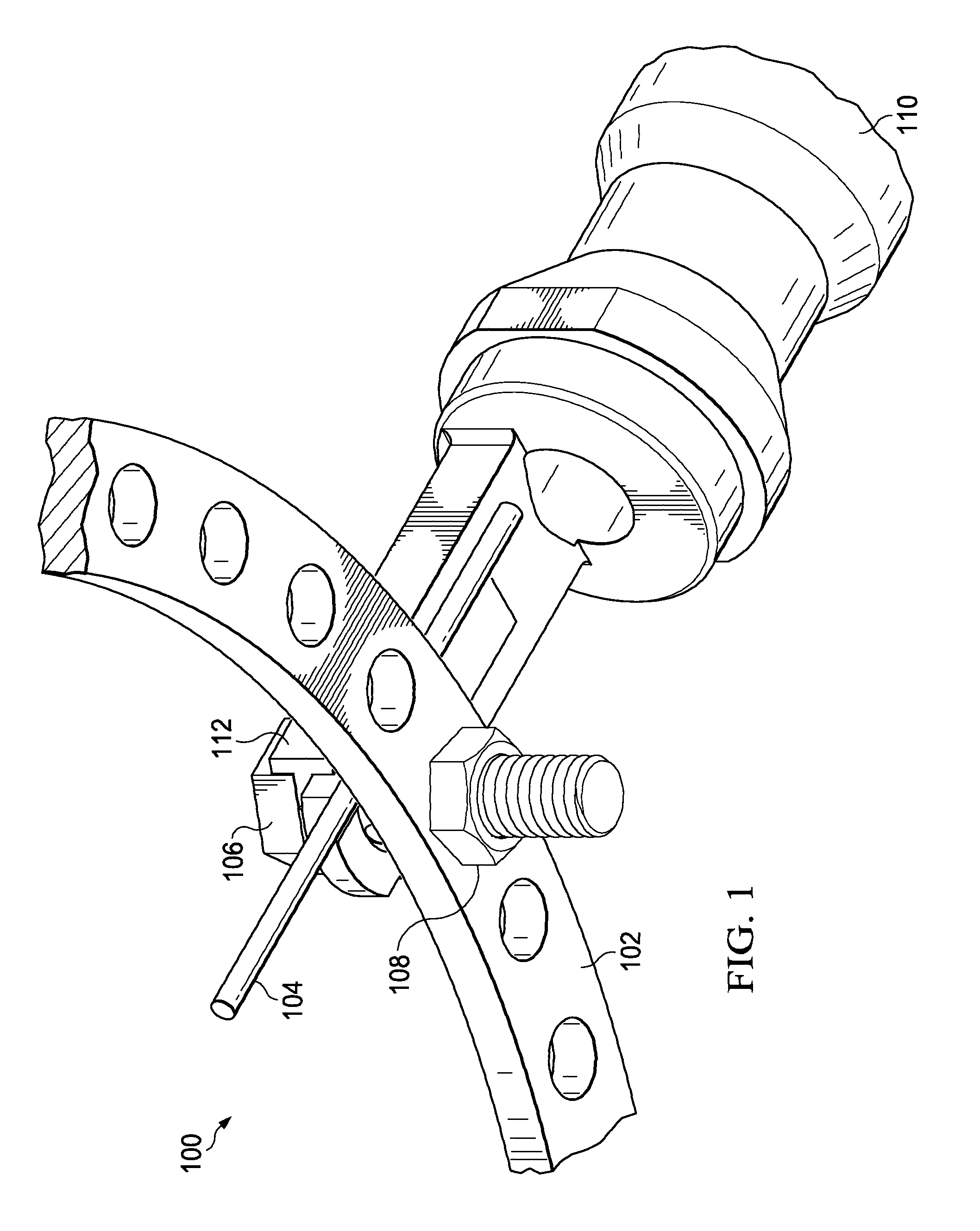
[0026]FIG. 1 illustrates a bottom elevational view of a wire fixation system 100, in accordance with one embodiment of the present disclosure. The wire fixation system 100 comprises an external fixator frame 102, a wire 104, a wire fixation bolt 106, a nut 108, and a wire tensioner 110 comprising a wire fixation tip 112. In the disclosed embodiments, the wire 104 may be tensioned against the wire fixation bolt 106 and only two tools—the wire tensioner 110 and a wrench (not shown)—may be needed to tension and secure the wire 104 relative to the external fixator frame 102. Each individual component is described below in more...


PUM


Abstract

A wire tensioner tip for use with a wire fixation bolt. First and second wires may be anchored to and tensioned across an external fixator frame with first and second wire tensioners. The first and second wires may be anchored at first anchor locations with first and second wire fixation bolts. First and second wire tensioner tips may engage with third and fourth wire fixation bolts, thereby preventing the third and fourth wire fixation bolts from rotating. The first and second wires may be tensioned to a desired tension with the first and second wire tensioners at the same time to prevent over-tensioning or under-tensioning. The first and second wires may be anchored at second anchor locations with third and fourth wire fixation bolts. By engaging the wire fixator bolts with the wire tensioning tips, fewer tools are required and one medical professional can tension two wires at once.

Description

TECHNICAL FIELD[0001]The present disclosure relates to a wire tensioner for use with an external fixator frame, wires, and wire fixation bolts, and more particularly, to an improved wire tensioner tip for engaging directly with a wire fixation bolt.BACKGROUND[0002]External orthopedic fixation devices are commonly used in the treatment of limb injuries and deformations including skeletal fractures, soft tissue injuries, delayed union of skeletal bones resulting from slow healing, non-union of skeletal bones involving unhealed bones, mal-union of bones resulting from the improper healing of broken or fractured bones, congenital deformities resulting from bones developing in a mal-position, and bone widening or twisting. Medical procedures involving external orthopedic fixation devices include limb lengthening, deformity correction, and the treatment of fractures, mal-unions, non-unions, and bone defects. Typically, external fixator systems may be placed on a subject's (e.g., a human o...

Claims


Application Information

Patent Timeline
Patent Type & Authority Patents(United States)
IPC IPC(8): A61B17/62A61B17/66A61B17/56
CPCA61B17/66A61B17/62A61B2017/564A61B17/8869
Inventor SAMCHUKOV, MIKHAIL L.ROSS, JOHN DAVIDCHERKASHIN, ALEXANDER M.BIRCH, JOHN G.
Owner TEXAS SCOTTISH RITE HOSPITAL FOR CHILDREN
Why Eureka
Try Eureka