
High speed, high density electrical connector with shielded signal paths

a high-density, electrical connector technology, applied in the direction of coupling device connection, coupling protective earth/shielding arrangement, electrical apparatus, etc., can solve the problems of constant mismatch, or tolerance, electrical interference between adjacent signal conductors, and the overall length of the connector may decreas

Active Publication Date: 2016-09-20
AMPHENOL CORP
View PDF246 Cites 106 Cited by
  • Summary
  • Abstract
  • Description
  • Claims
  • Application Information

AI Technical Summary

Problems solved by technology

Electronic systems generally have gotten smaller, faster, and functionally more complex.
In a high density, high speed connector, electrical conductors may be so close to each other that there may be electrical interference between adjacent signal conductors.
However, this constant mismatch, or tolerance, may become a decreasing percentage of the connector's overall length as the connector gets longer.
Therefore, manufacturing tolerances may be tighter for larger connectors, which may increase manufacturing costs.

Method used


Image

  • High speed, high density electrical connector with shielded signal paths
  • High speed, high density electrical connector with shielded signal paths
  • High speed, high density electrical connector with shielded signal paths

Examples


Embodiment Construction

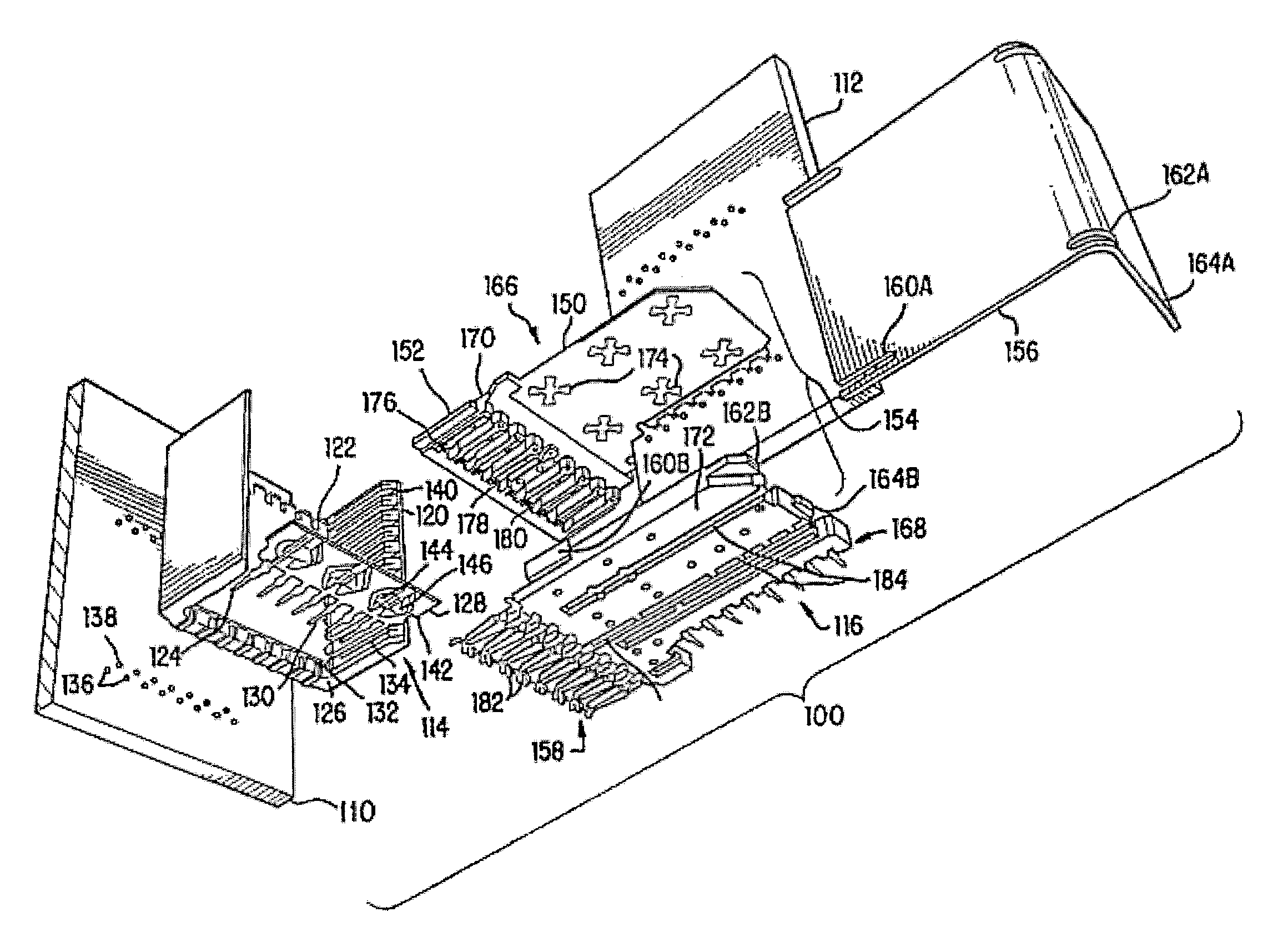
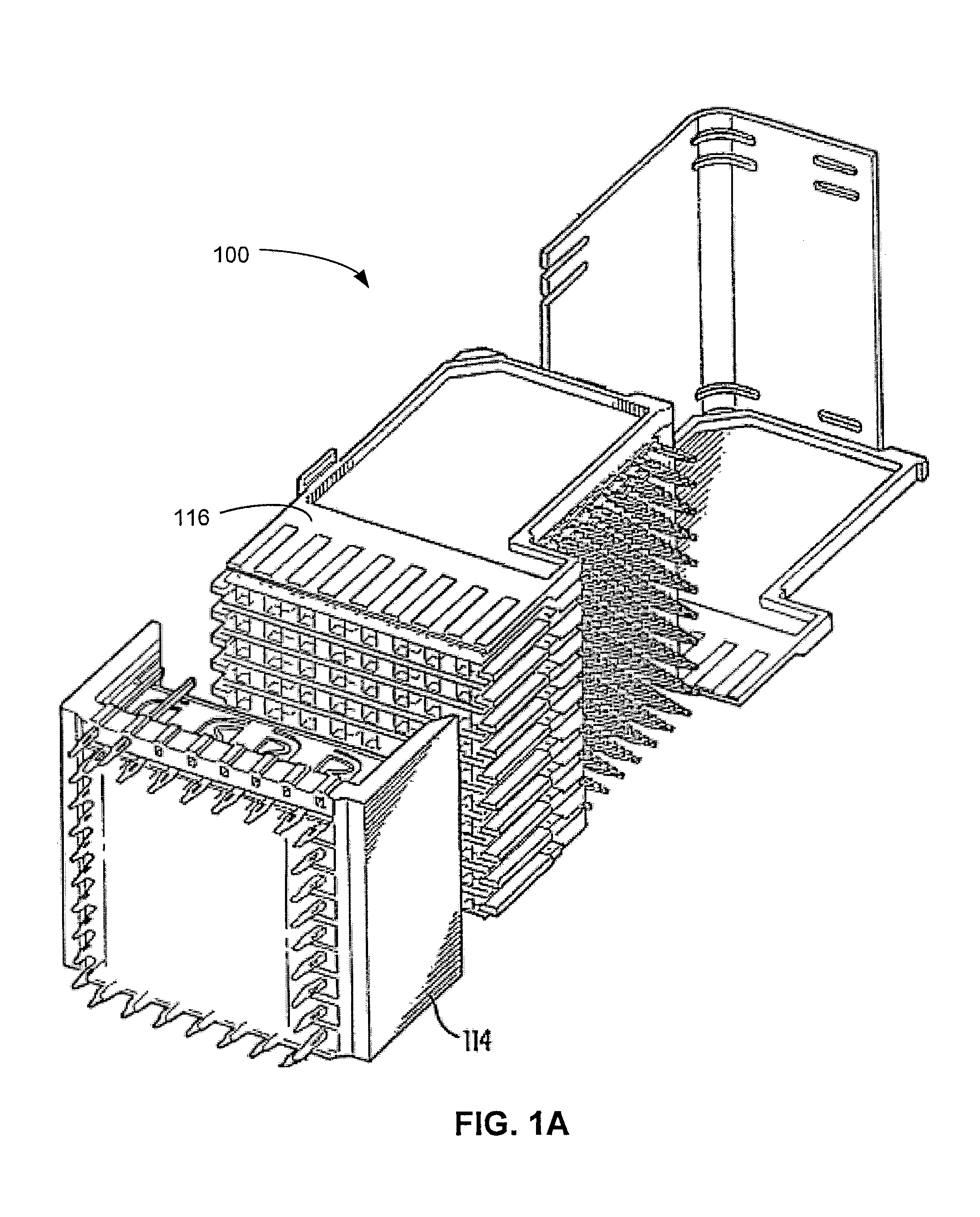
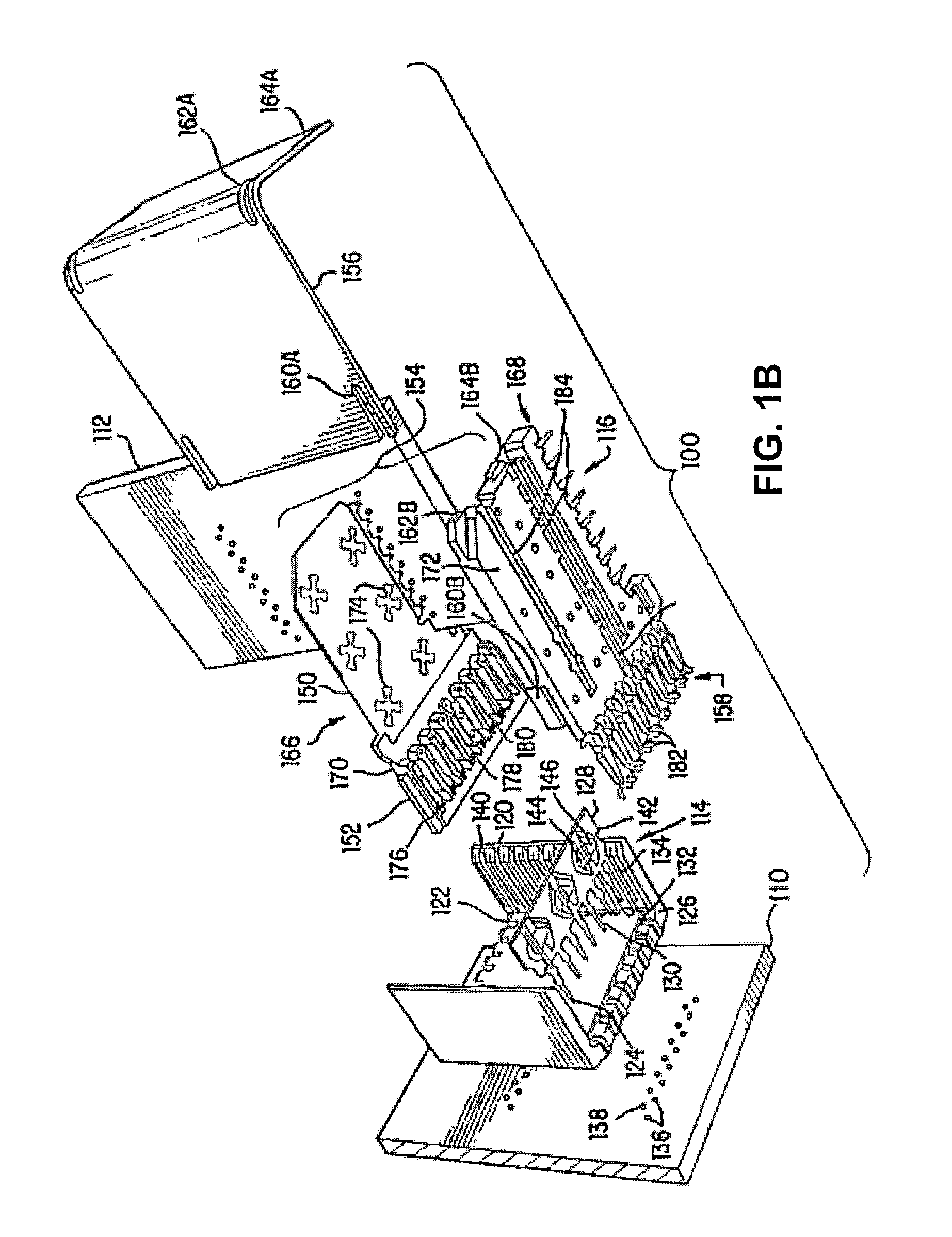
[0084]Designs of an electrical connector are described herein that improve signal integrity for high frequency signals, such as at frequencies in the GHz range, including up to about 25 GHz or up to about 40 GHz or higher, while maintaining high density, such as with a spacing between adjacent mating contacts on the order of 2 mm or less, including center-to-center spacing between adjacent contacts in a column of between 0.75 mm and 1.85 mm, between 1 mm and 1.75 mm, or between 2 mm and 2.5 mm (e.g., 2.40 mm), for example. Spacing between columns of mating contact portions may be similar, although there is no requirement that the spacing between all mating contacts in a connector be the same.

[0085]The present disclosure is not limited to the details of construction or the arrangements of components set forth in the following description and / or the drawings. Various embodiments are provided solely for purposes of illustration, and the concepts described herein are capable of being pr...


PUM

PropertyMeasurementUnit
thickaaaaaaaaaa
thickaaaaaaaaaa
thickaaaaaaaaaa

Abstract

A modular electrical connector with separately shielded signal conductor pairs. The connector may be assembled from modules, each containing a pair of signal conductors with surrounding partially or fully conductive material. Modules of different sizes may be assembled into wafers, which are then assembled into a connector. Wafers may include lossy material. In some embodiments, shielding members of two mating connectors may each have compliant members along their distal portions, such that, the shielding members engage at points of contact at multiple locations, some of which are adjacent the mating edge of each of the mating shielding members.

Description

RELATED APPLICATIONS[0001]This Application claims priority under 35 U.S.C. §119(e) to U.S. Provisional Application Ser. No. 61 / 930,411, entitled “HIGH SPEED, HIGH DENSITY ELECTRICAL CONNECTOR WITH SHIELDED SIGNAL PATHS” filed on Jan. 22, 2014 and to U.S. Provisional Application Ser. No. 62 / 078,945, entitled “VERY HIGH SPEED, HIGH DENSITY ELECTRICAL INTERCONNECTION SYSTEM WITH IMPEDANCE CONTROL IN MATING REGION” filed on Nov. 12, 2014, both of which are herein incorporated by reference in their entireties.BACKGROUND[0002]This invention relates generally to electrical connectors used to interconnect electronic assemblies.[0003]Electrical connectors are used in many electronic systems. It is generally easier and more cost effective to manufacture a system as separate electronic assemblies, such as printed circuit boards (“PCBs”), which may be joined together with electrical connectors. A known arrangement for joining several printed circuit boards is to have one printed circuit board s...

Claims


Application Information

Patent Timeline
Patent Type & Authority Patents(United States)
IPC IPC(8): H01R13/648H01R13/6585H01R13/6599H01R13/6598
CPCH01R13/6599H01R13/6585H01R13/6598H01R12/724H01R12/737H01R13/518H01R13/6587Y10T29/4922Y10T29/49222H01R13/025H01R43/24
Inventor CARTIER, JR., MARC B.DUNHAM, JOHN ROBERTGAILUS, MARK W.GIRARD, JR., DONALD A.MANTER, DAVIDPITTEN, TOMSIVARAJAN, VYSAKHSNYDER, MICHAEL JOSEPH
Owner AMPHENOL CORP
Learn More