Lighting device for the interior furnishing of an aircraft cabin

a technology for aircraft cabins and lighting devices, which is applied to aircraft floors, aircraft components, aircraft accessories, etc., can solve the problems of achieve the effect of facilitating the disassembly of the trim panels, which no longer comprise lighting elements, and no longer removing the lighting of the cabin

Active Publication Date: 2016-09-27
AIRBUS JET CENT
View PDF9 Cites 1 Cited by
  • Summary
  • Abstract
  • Description
  • Claims
  • Application Information

AI Technical Summary

Benefits of technology

[0010]To this end, the present invention relates to an aircraft fuselage comprising a structural wall and a floor delimiting a cabin for passengers, said wall being covered by a plurality of adjacent trim panels arranged in succession in the longitudinal direction of the fuselage and spaced from one another with a gap between two adjacent panels, each panel also being fixed to the wall and having a concave shape adapted to the shape of the fuselage, at least one lighting device being disposed at the level of at least one of the gaps, and being arranged perpendicularly to a longitudinal axis of the fuselage, said lighting device comprising a housing fixed to the wall, said housing being provided with an opening on a face oriented toward the interior of said cabin, said housing further comprising at least one lighting element making it possible to light the cabin through the gap.
[0011]Thus, said housing of the lighting device and the trim panels have no mechanical connection to one another besides a point contact. The disassembly of the trim panels, which no longer comprise lighting elements, is thus facilitated and, moreover, this disassembly no longer removes the lighting of the cabin.

Problems solved by technology

The disassembly of the trim panels, which no longer comprise lighting elements, is thus facilitated and, moreover, this disassembly no longer removes the lighting of the cabin.

Method used


Image

  • Lighting device for the interior furnishing of an aircraft cabin
  • Lighting device for the interior furnishing of an aircraft cabin
  • Lighting device for the interior furnishing of an aircraft cabin

Examples


Embodiment Construction

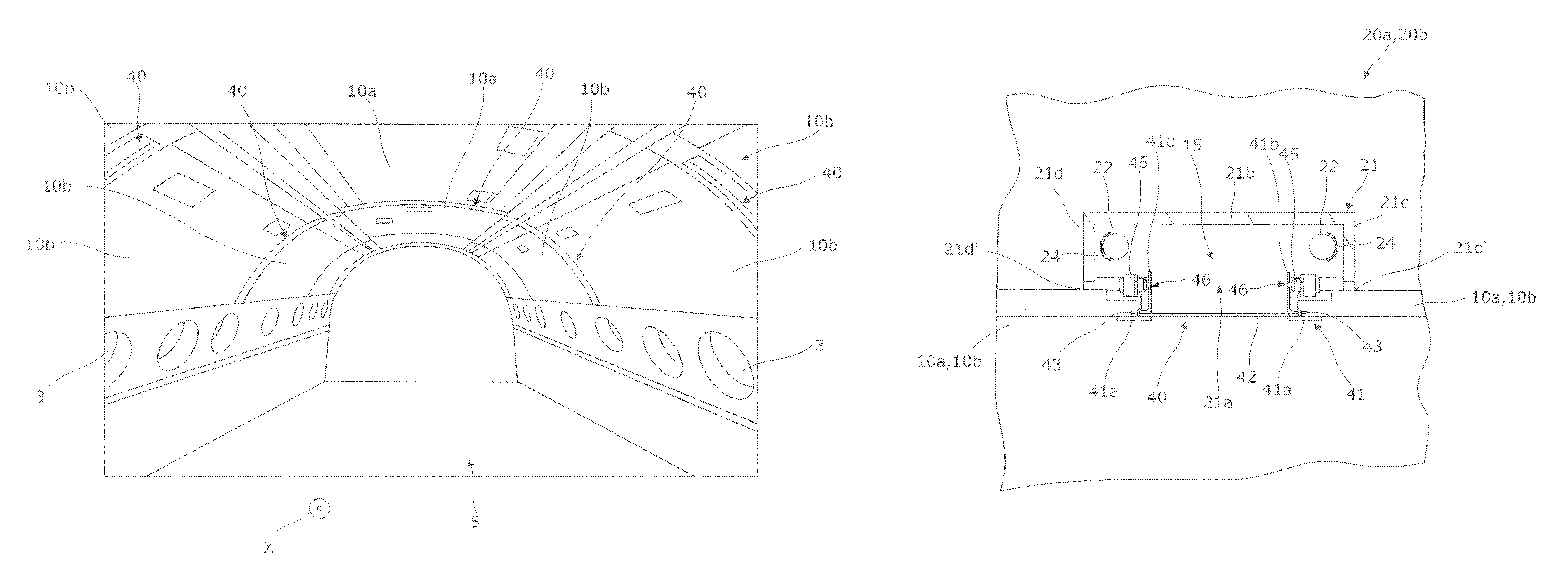
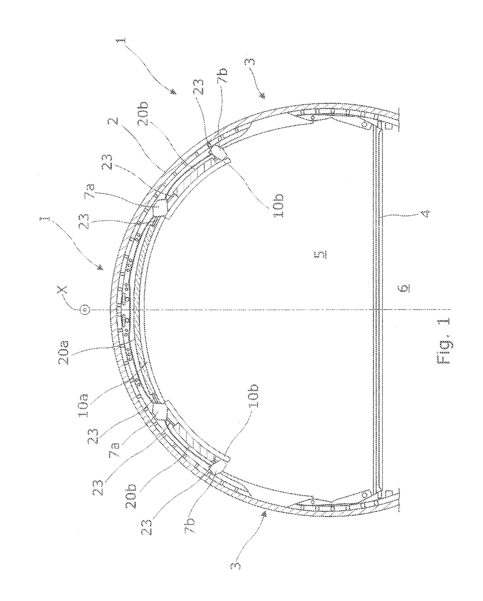
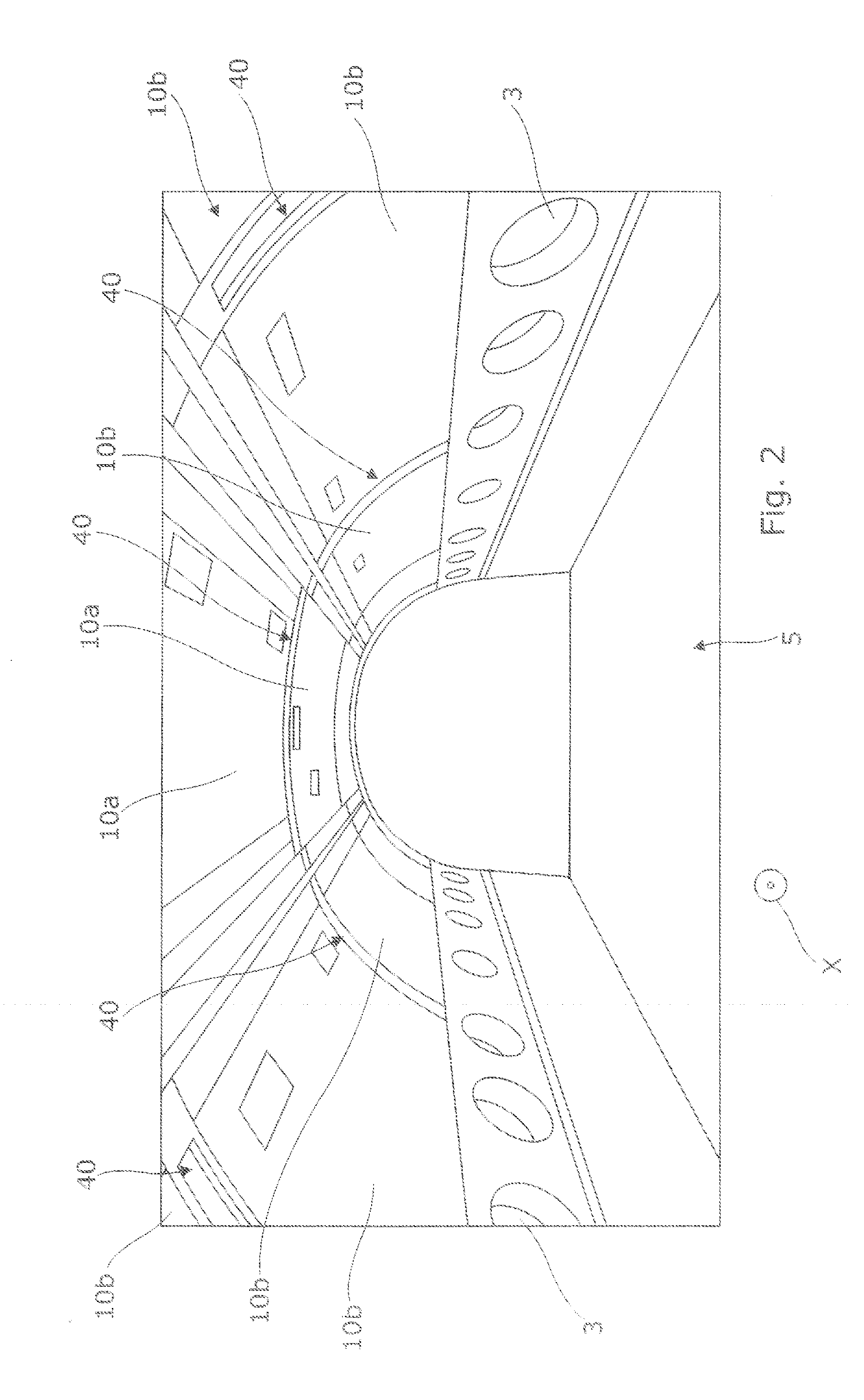
[0021]The fuselage of an aircraft 1, shown in part in FIG. 1, usually comprises a substantially cylindrical structural wall 2 incorporating side windows 3, and a floor 4 separating the interior of the fuselage into an upper compartment 5 for the passengers, denoted hereinafter as the “passenger cabin”, and a lower compartment 6 for the cargo in particular.

[0022]As is known, the structural wall 2 comprises, on each side of the fuselage, at least two longitudinal rails 7a, 7b (which may comprise a plurality of sections), fixed to said wall by fixing elements, such as connecting rods and attachment angles (not shown in the figures). Each rail 7a, 7b supports different technical installations (not shown in the figures), as described further above, and an interior furnishing so as to hide the rails, the structural wall 2 and the technical installations.

[0023]The rails 7a, 7b run in parallel along the length of the fuselage in the longitudinal direction X and are disposed, on each side of...


PUM


Abstract

An aircraft fuselage comprising a structural wall and a floor delimiting a cabin for passengers, said wall being covered by a plurality of adjacent trim panels arranged in succession in the longitudinal direction of the fuselage and spaced from one another with a gap between two adjacent panels. Each panel is also fixed to the wall and has a concave shape adapted to the shape of the fuselage. At least one lighting device is disposed at the level of at least one of the gaps and is arranged perpendicularly to a longitudinal axis of the fuselage. The lighting device comprises a housing fixed to the wall. The housing is provided with an opening on a face oriented toward the interior of said cabin. The housing further comprises at least one lighting element making it possible to light the cabin through the gap.

Description

CROSS-REFERENCES TO RELATED APPLICATIONS[0001]This application claims the benefit of the French patent application No. 1453979 filed on Apr. 30, 2014, the entire disclosures of which are incorporated herein by way of reference.BACKGROUND OF THE INVENTION[0002]The invention relates to the furnishing of an aircraft cabin. More particularly, the invention relates to a lighting device for hiding the gap at the junction of two trim panels of an aircraft cabin.[0003]As is known, technical installations intended for the ventilation system, the oxygen network or the electrical network of the aircraft are arranged in the passenger cabin. These installations are attached to longitudinal rails fixed to the fuselage and arranged on the sides of the fuselage, both in the upper part (upper rails) of the fuselage and in the intermediate part at the level of the windows of the fuselage (lower rails).[0004]In order to hide these installations from the view of the passengers, the cabin comprises an i...

Claims


Application Information

Patent Timeline
Patent Type & Authority Patents(United States)
IPC IPC(8): B64D11/00B64C1/18
CPCB64D11/00B64C1/18B64D2011/0038
Inventor MARIAT, SYLVAINDESTIEU, JEAN-CYRILLECHANTAL, BERANGERLEGROS, JEAN-LUCFERRERE, NICOLASTAFFARELLO, PASCAL
Owner AIRBUS JET CENT
Why Eureka
Try Eureka