Valve flow adjustment device

a technology of valve flow and adjustment device, which is applied in the direction of valve details, valve arrangement, operating means/releasing devices, etc., can solve the problems of increasing the cost of known devices, difficult to remove and install, and additional time the control valve is out of service, so as to quickly change the maximum flow capacity of the valve, improve productivity, and minimize drawbacks

Active Publication Date: 2009-12-01
FISHER CONTROLS INT LLC
View PDF18 Cites 1 Cited by
  • Summary
  • Abstract
  • Description
  • Claims
  • Application Information

AI Technical Summary

Benefits of technology

[0012]Having a projection on the valve stem permits the collar to simply be installed on the valve stem and rotated to vary the valve stem travel between different predetermined settings. Depending on the orientation of the collar, if the relatively most shallow groove is oriented toward the projection, it will contact the projection and limit the valve stem travel based on the distance between the top of the collar and the top of the groove. Alternatively, if a deeper groove is oriented toward the projection, the projection will contact the top of the deeper groove, thus limiting the travel by even less of the overall height of the collar. Thus, the collar may be rotated to adjust between a plurality of predetermined valve stem travel limits.
[0013]The collar may be held in place via gravity or a resilient member such as a coil spring or other means. Advantageously, the collar position may be conveniently adjusted without tools or manipulation of bolts or screws, and the collar may be made without some of the special machining and assembly techniques associated therewith. In turn, the device can be quite small and compact, allowing for shorter, lighter and less expensive valve assemblies having fewer parts. Such devices will require less time to adjust and, therefore, are more likely to permit rapid changes in maximum flow capacity during normal system operation, between strokes of the valve stem.
[0015]Depending on the configuration chosen, the device minimizes the drawbacks of the prior art while permitting a user to quickly change the maximum flow capacity of a valve entirely via action taken outside of, or external to, the valve housing. Indeed, the operator may be able to make a flow adjustment without use of tools, and between strokes of the valve stem, depending on the cycle time. This not only improves productivity by not having to shut down the fluid system, but also reduces operator time and effort, which can have a significant impact financially, as well as to the comfort of an operator working in inclement weather.

Problems solved by technology

However, replacement of a valve plug and / or valve seat can necessitate disassembly and reassembly of the valve, which results in additional labor, and additional time the control valve is out of service.
However, the known devices tend to be fairly expensive and difficult to remove and install.
This may be due to the tendency to require serrations or threads along the valve stem, as well as along the internal surface of the travel limiting device which engages the valve stem.
Also, the devices tend to require removable bolts to fasten pieces together, which may create problems concerning adequate access for manipulation of tools to assemble and disassemble the device during adjustments, as well as having to deal with multiple loose parts which require care in handling so as not to drop them, while at the same time the difficulty of achieving proper thread alignment when installing bolts, etc.
The more difficult and time consuming manipulation involved with the prior art devices can be particularly challenging when an operator is wearing gloves, such as may be necessary in a cold environment.

Method used


Image

  • Valve flow adjustment device
  • Valve flow adjustment device
  • Valve flow adjustment device

Examples


Embodiment Construction

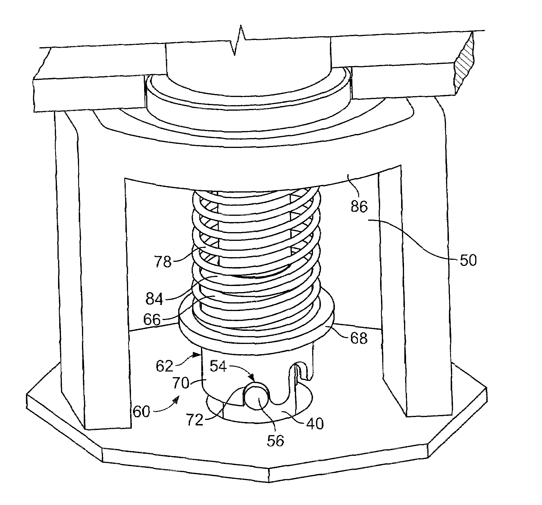
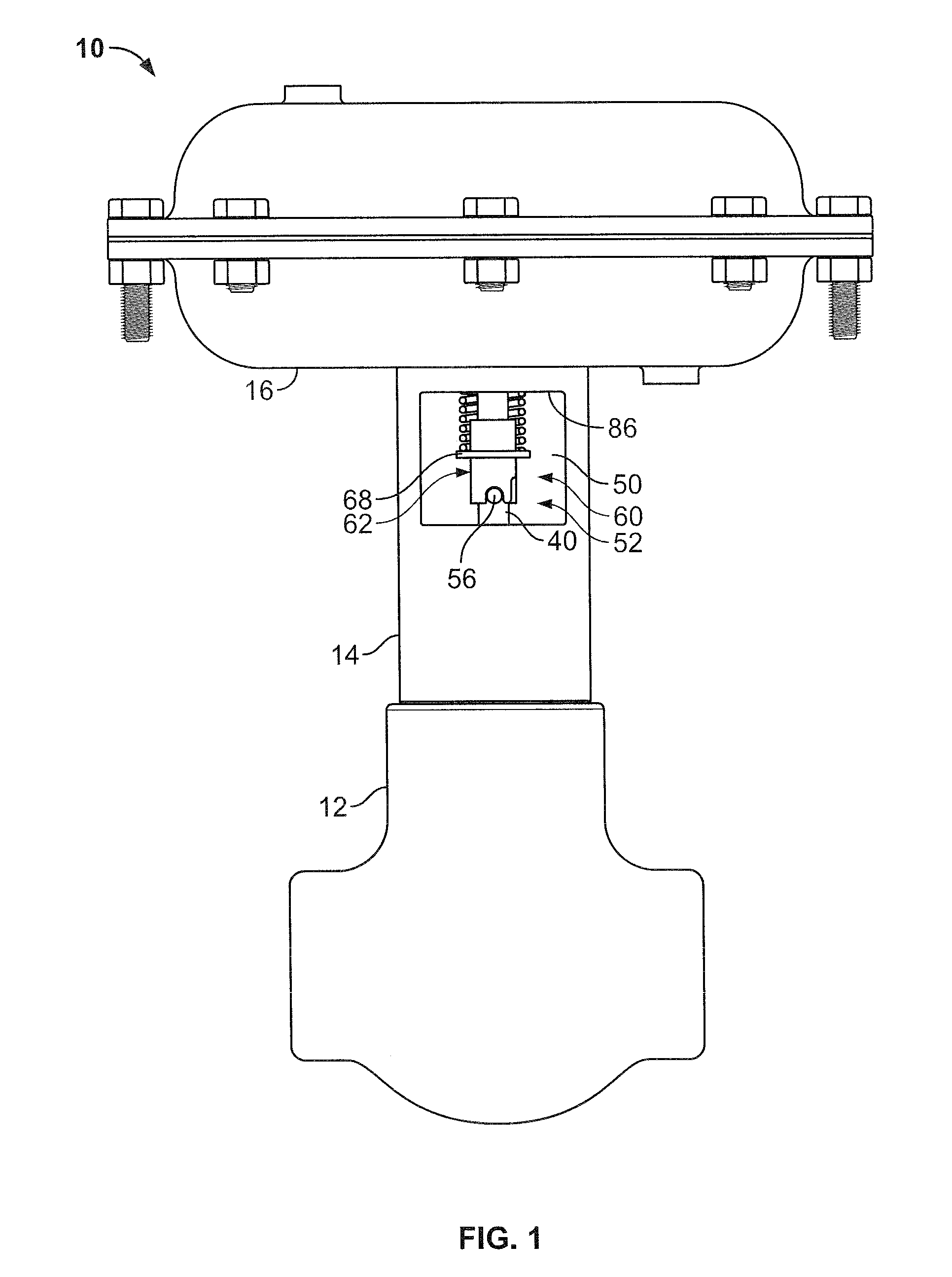
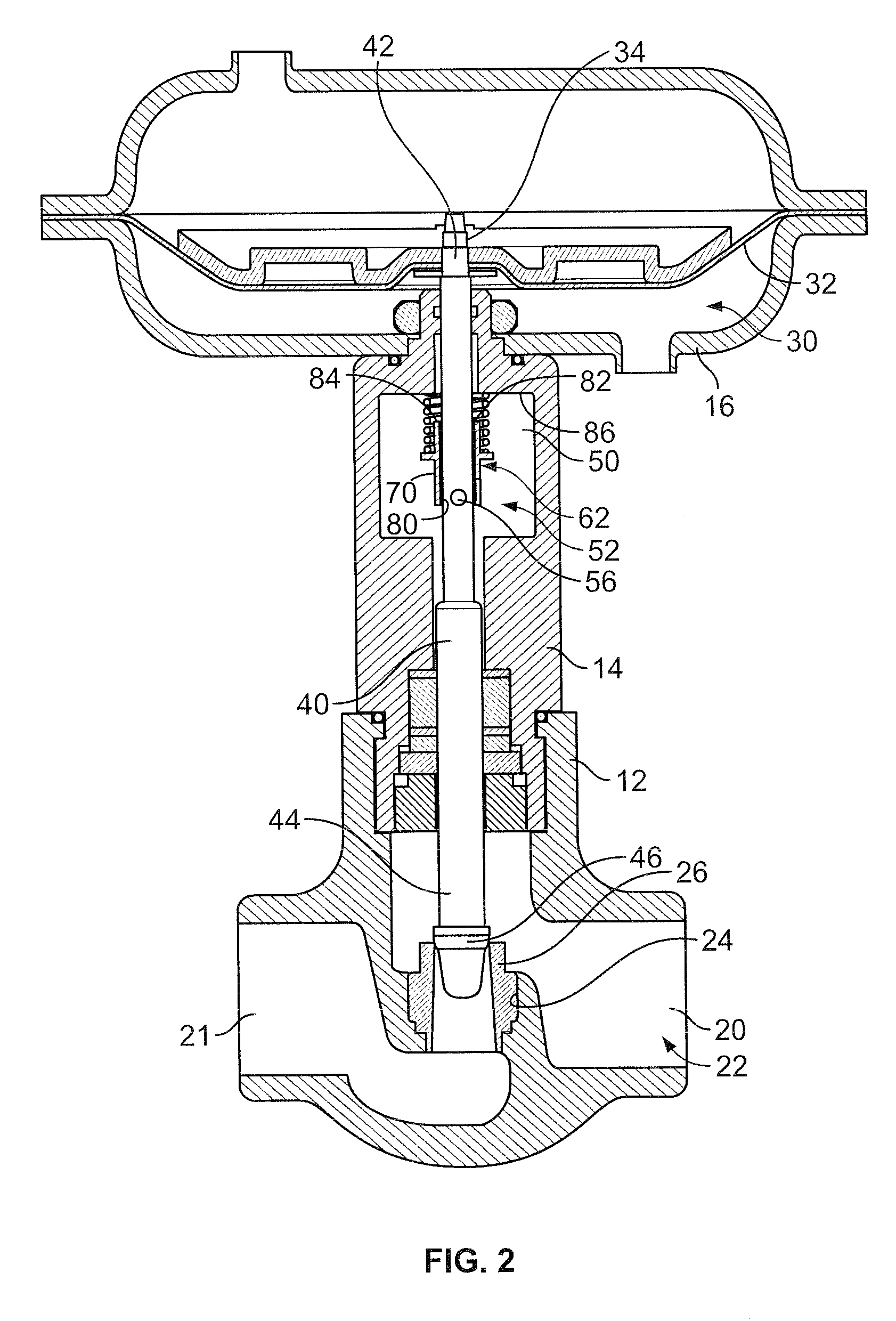
[0026]Referring now to the drawings, FIGS. 1 and 2 show an example of a control valve assembly 10 that includes a valve body 12 connected to a bonnet 14. The bonnet 14, in turn, is connected to a diaphragm casing 16. The diaphragm casing 16 houses a sliding stem actuator, which may take other forms. The sliding stem actuator can be of any suitable type for use with control valves. The control valve assembly 10 may be joined by conventional methods, such as flange mounting, to fluid piping components within a larger process control system.

[0027]Passing through the bonnet 14 is a valve stem 40. Valve stem 40 is to be coupled to and driven by the sliding stem actuator at its proximal or upper end 42. The valve stem 40 passes through the bonnet 14 and downward into the valve body 12. In this example, coupled to the lower end 44 of the valve stem 40 is a valve plug 46. The valve plug 46 includes a seating surface on its lower side. It will be appreciated that the valve stem 40 and valve ...


PUM


Abstract

A valve with a flow adjustment device in the form of a valve stem travel limiter includes a collar having a passage therethrough to receive a valve stem having a projection, the collar further includes a plurality of grooves having different depths. The flow adjustment device may be assembled to a valve stem to permit a plurality of different predetermined valve stem travel limits corresponding to respective different maximum flow capacities of the valve.

Description

FIELD OF THE DISCLOSURE[0001]The disclosure relates generally to control valves having a valve stem movable for flow rate adjustment and, more particularly, to travel limiters for such valve stems to adjust maximum available flow rate.BACKGROUND[0002]Typically, a control valve includes a fluid inlet passage coupled through an orifice to a fluid outlet passage and a closure member disposed in the orifice, which controls the amount of fluid flow therethrough. The closure member may include a valve plug having a surface which engages the orifice forming a valve seat. During operation of a process control system, a process controller may issue a command signal to a control valve to move the valve plug toward or away from engagement with the valve seat to provide a desired fluid flow through the orifice and, therefore, the control valve.[0003]Control valves typically experience variable process conditions during their lifetime. A gas well, for example, may have high pressure when first d...

Claims


Application Information

Patent Timeline
Patent Type & Authority Patents(United States)
IPC IPC(8): F16K51/00
CPCF16K31/126F16K1/523
Inventor GETHMANN, DOUGLAS PAUL
Owner FISHER CONTROLS INT LLC
Why Eureka
Try Eureka