Motion tracking based on fast image acquisition

a motion tracking and image acquisition technology, applied in the field of magnetic resonance imaging, can solve the problems of serious image quality and image quality degradation, and achieve the effect of reducing the overall speed of the examination process

Active Publication Date: 2016-09-27
KONINKLJIJKE PHILIPS NV
View PDF12 Cites 12 Cited by
  • Summary
  • Abstract
  • Description
  • Claims
  • Application Information

AI Technical Summary

Benefits of technology

[0028]This has the effect of correcting for the detected motion such that in a next iteration the second calibration scan may be performed using the updated second scan geometry. As soon as this process converges, the MRI scan used for diagnostic purpose may use the updated predefined scan geometry which is associated with the new position of the target volume.
[0056]This may be advantageous in that the system may be fully integrated into the workflow similar to a scan preparation phase (i.e. without user interaction).

Problems solved by technology

Motion during an MRI examination can seriously compromise image quality.
This may lead to a bad image quality due to motion artifacts or a wrong anatomy which is imaged.

Method used


Image

  • Motion tracking based on fast image acquisition
  • Motion tracking based on fast image acquisition
  • Motion tracking based on fast image acquisition

Examples


Embodiment Construction

[0070]In the following, like numbered elements in the figures are either similar elements or perform an equivalent function. Elements which have been discussed previously will not necessarily be discussed in later figures if the function is equivalent.

[0071]Various structures, systems and devices are schematically depicted in the figures for purposes of explanation only and so as to not obscure the present invention with details that are well known to those skilled in the art. Nevertheless, the attached figures are included to describe and explain illustrative examples of the disclosed subject matter.

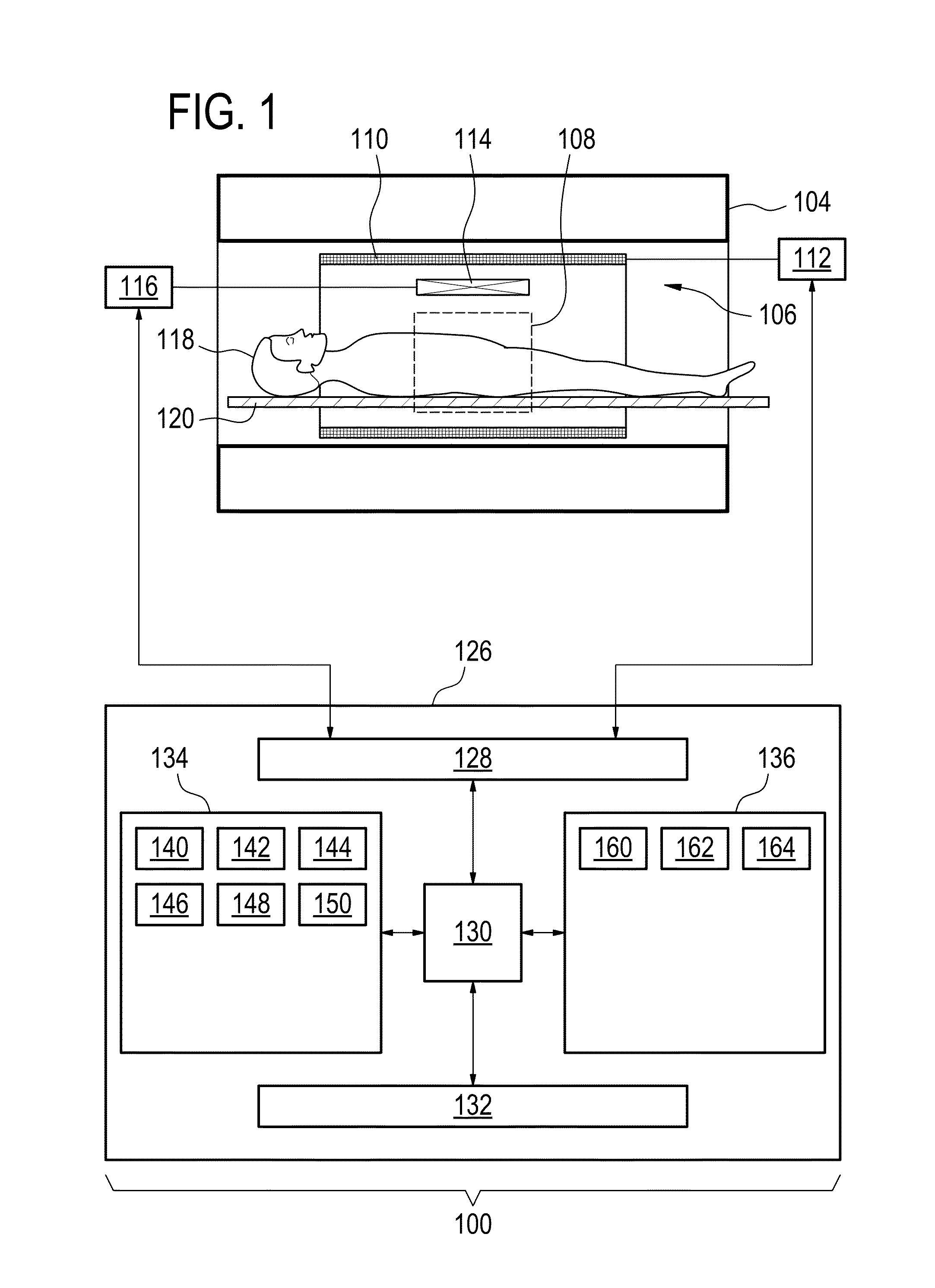
[0072]FIG. 1 illustrates an example of a magnetic resonance imaging system 100. The magnetic resonance imaging system 100 comprises a magnet 104. The magnet 104 is a superconducting cylindrical type magnet 104 with a bore 106 through it. The use of different types of magnets is also possible for instance it is also possible to use both a split cylindrical magnet and a so called open mag...


PUM


Abstract

A magnetic resonance imaging (MRI) system including a memory for storing machine executable instructions and a processor for controlling the magnetic resonance imaging system. The MRI system for performing a plurality of MRI scans for acquiring magnetic resonance data from a target volume of a patient in accordance with respective predefined scan geometries. The execution of the machine executable instructions causes the processor to control the MRI system to at least: perform a first calibration scan; perform a second calibration scan; generate geometry transformation data; determine a deviation of the target volume caused by a movement of the patient; update each of the predefined scan geometries and the second scan geometry as a function of the geometry transformation data; and perform at least one MRI scan of the plurality of MRI scans to acquire image data in accordance with the respective updated predefined scan geometry.

Description

CROSS REFERENCE TO RELATED APPLICATIONS[0001]This application claims the benefit of U.S. provisional application Ser. No. 61 / 693,408 filed Aug. 27, 2012, and European provisional application Ser. No. 12181828.0 filed Aug. 27, 2012, both of which are incorporated herein by reference.TECHNICAL FIELD[0002]The invention relates to magnetic resonance imaging, in particular to motion tracking based on fast image acquisition.BACKGROUND OF THE INVENTION[0003]Motion during an MRI examination can seriously compromise image quality. In a typical examination, multiple scans are performed. The geometry of these scans is planned on a survey scan which is one of the first scans that is performed. If the patient moves after the acquisition of the survey scan, the scanned location is different from the planned location throughout the following part of the examination. This may lead to a bad image quality due to motion artifacts or a wrong anatomy which is imaged. As a consequence the total time of t...

Claims


Application Information

Patent Timeline
Patent Type & Authority Patents(United States)
IPC IPC(8): G01R33/58G01R33/565G01R33/483
CPCG01R33/58G01R33/56509G01R33/4835
Inventor NIELSEN, TIMBOERNERT, PETERSENEGAS, JULIEN
Owner KONINKLJIJKE PHILIPS NV
Why Eureka
Try Eureka