Transflective display device, electronic apparatus, and method of driving transflective display device

a technology of display device and display device, which is applied in static indicating device, instruments, non-linear optics, etc., can solve the problem of reducing the performance of reflective display

Active Publication Date: 2016-09-27
JAPAN DISPLAY INC
View PDF19 Cites 5 Cited by
  • Summary
  • Abstract
  • Description
  • Claims
  • Application Information

AI Technical Summary

Benefits of technology

[0009]For the foregoing reasons, there is a need for a transflective display device that is capable of performing transmissive display while maintaining the same reflective display performance as the reflective display device, an electronic apparatus provided with the same, and a method of driving the transflective display device.

Problems solved by technology

That is, in a case of largely securing the transmissive display region to increase transmissive display performance, since it cannot help reducing the reflective display region by the increase, reflective display performance decreases.

Method used


Image

  • Transflective display device, electronic apparatus, and method of driving transflective display device
  • Transflective display device, electronic apparatus, and method of driving transflective display device
  • Transflective display device, electronic apparatus, and method of driving transflective display device

Examples


Embodiment Construction

[0057]Hereinafter, an example of implementing a technology of the present disclosure (hereinafter, simply referred to as an “embodiment”) will be described in detail in the following order with reference to the attached drawings.

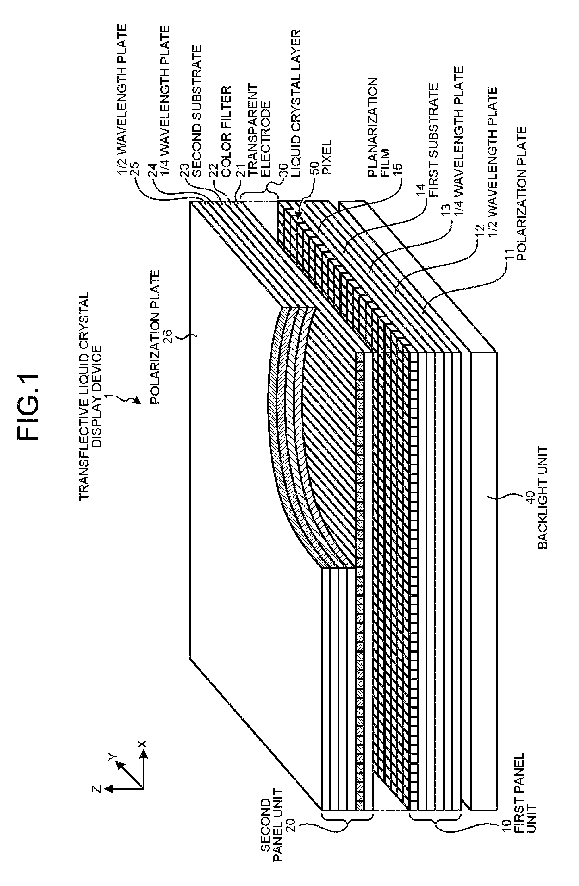
[0058]1. Transflective Display Device to Which Present Disclosure is Applied

[0059]1-1. Transflective Display Device Capable of Color Display

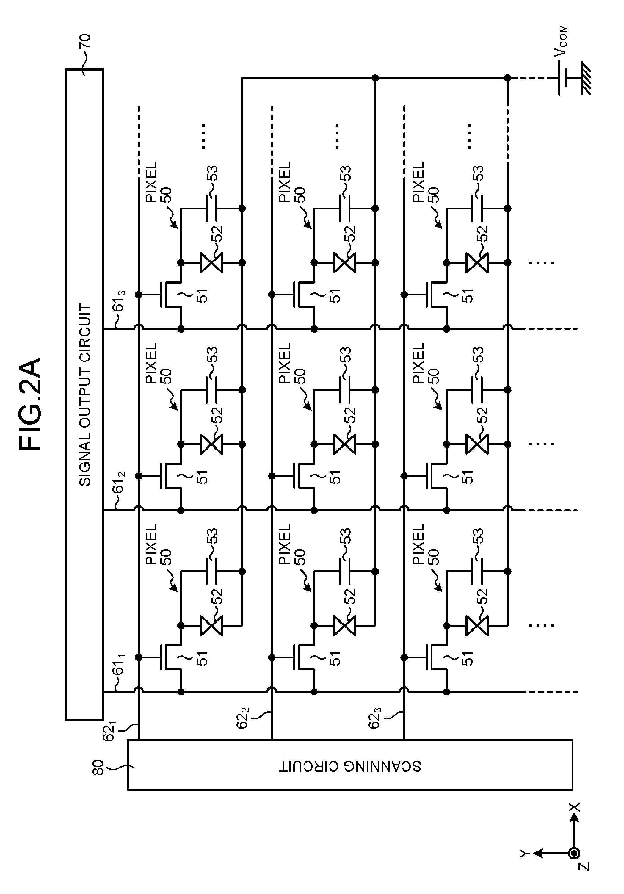
[0060]1-2. Basic Pixel Circuit

[0061]1-3. Pixel and Sub-pixel

[0062]1-4. Examination on Electrode Structure of Pixel Portion

[0063]2. Description of Embodiment

[0064]2-1. Driving method of Liquid Crystal Display Panel

[0065]2-2. MIP Technology

[0066]2-3. Display Mode

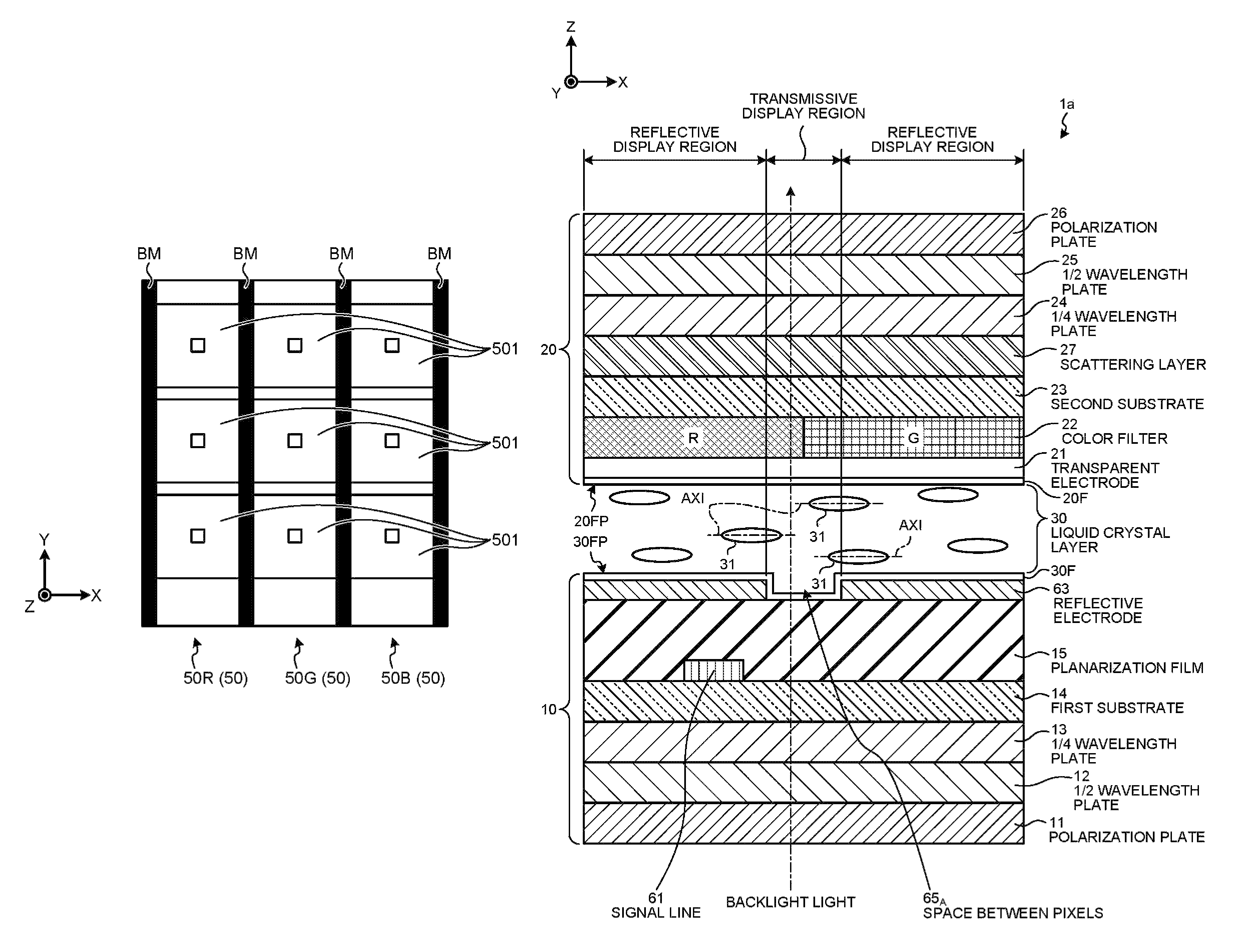
[0067]2-4. Black Matrix and Overlapping of Color Filter

[0068]2-5. Orientation of Liquid Crystal Molecule

[0069]2-6. Scattering Layer

[0070]2-7. Specific Example

[0071]3. Modification

[0072]4. Electronic Apparatus

[0073]5. Aspects of Present Disclosure

1. Transflective Display Device to which Present Disclosure is Applied

[0074]The technology of the present disclosure is a...


PUM

PropertyMeasurementUnit
angleaaaaaaaaaa
angleaaaaaaaaaa
angleaaaaaaaaaa

Abstract

According to an aspect, a transflective display device, includes a first substrate on which a first orientation film and a plurality of reflective electrodes formed for each of pixels are provided; a second substrate on which a second orientation film and a transparent electrode that is opposite to the reflective electrodes are provided; and a liquid crystal layer including a plurality of liquid crystal molecules provided between the first substrate and the second substrate. A direction of long axis of the liquid crystal molecules is parallel to surfaces of the first and second orientation films and twisted between the first substrate and the second substrate. The reflective electrode is configured to perform reflective display, and a space between the reflective electrodes of the adjacent pixels is configured to perform transmissive display.

Description

CROSS REFERENCES TO RELATED APPLICATIONS[0001]The present application claims priority to Japanese Priority Patent Application JP 2012-243692 filed in the Japan Patent Office on Nov. 5, 2012, the entire content of which is hereby incorporated by reference.BACKGROUND[0002]1. Technical Field[0003]The present disclosure relates to a transflective display device, an electronic apparatus provided with the same, and a method of driving a transflective display device.[0004]2. Description of the Related Art[0005]Examples of a display device include a transmissive display device that performs display using transmitted light of backlight light on a rear surface side of a screen, and a reflective display device that performs display using reflected light of external light. The transmissive display device has characteristics that saturation is high, and a screen is easy to view under a dark environment. The reflective display device has characteristics that power consumption is low, and the scre...

Claims


Application Information

Patent Timeline
Patent Type & Authority Patents(United States)
IPC IPC(8): G02F1/1335G02F1/139G09G3/36
CPCG02F1/133555G02F1/1396G02F1/133553G09G3/3614G09G3/3648G09G2300/0456G09G2300/0857G02F1/133G02F1/1335G02F1/1337G02F1/1343
Inventor TAMAKI, MASAYA
Owner JAPAN DISPLAY INC
Why Eureka
Try Eureka