
Charge control device, charge control method, and charge control system

a control device and control method technology, applied in the direction of electric devices, battery/fuel cell control arrangements, transportation and packaging, etc., can solve the problems of secondary battery deterioration and replacement cost, and achieve the effect of suppressing the progress of deterioration

Active Publication Date: 2016-10-04
MITSUBISHI HEAVY IND ENG LTD
View PDF18 Cites 0 Cited by
  • Summary
  • Abstract
  • Description
  • Claims
  • Application Information

AI Technical Summary

Benefits of technology

The patent relates to a charge control system for a secondary battery. The system uses an effective current value to determine the optimal charging current, which is then supplied to the battery by the charge control unit. This allows the battery to be charged with the minimum amount of current, which can help to slow down deterioration caused by high temperatures. The technical effect of this system is to improve the efficiency and lifespan of secondary batteries used in various applications.

Problems solved by technology

When introducing the secondary battery to the electric vehicle, deterioration of the secondary battery has become an issue.
In the introduction of the secondary battery, there is a problem of the cost for replacement.

Method used


Image

  • Charge control device, charge control method, and charge control system
  • Charge control device, charge control method, and charge control system
  • Charge control device, charge control method, and charge control system

Examples


first embodiment

[0022]Hereinafter, an embodiment of the present invention will be described in detail with reference to the diagrams.

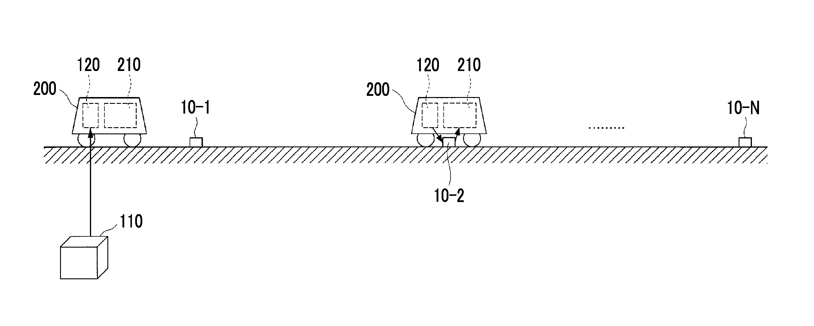
[0023]FIG. 1 is a schematic diagram showing an embodiment of a charge control system 100 according to a first embodiment of the present invention.

[0024]The charge control system 100 is a system that controls the charging of a secondary battery 210. The secondary battery 210 is provided in a vehicle 200 traveling on a path. On the path, N charging locations including charging devices 10-1 to 10-N (hereinafter, referred to as a charging device 10 when the charging devices 10-1 to 10-N are collectively referred to) are provided. In the present embodiment, one of the charging locations is provided at the end point of the path.

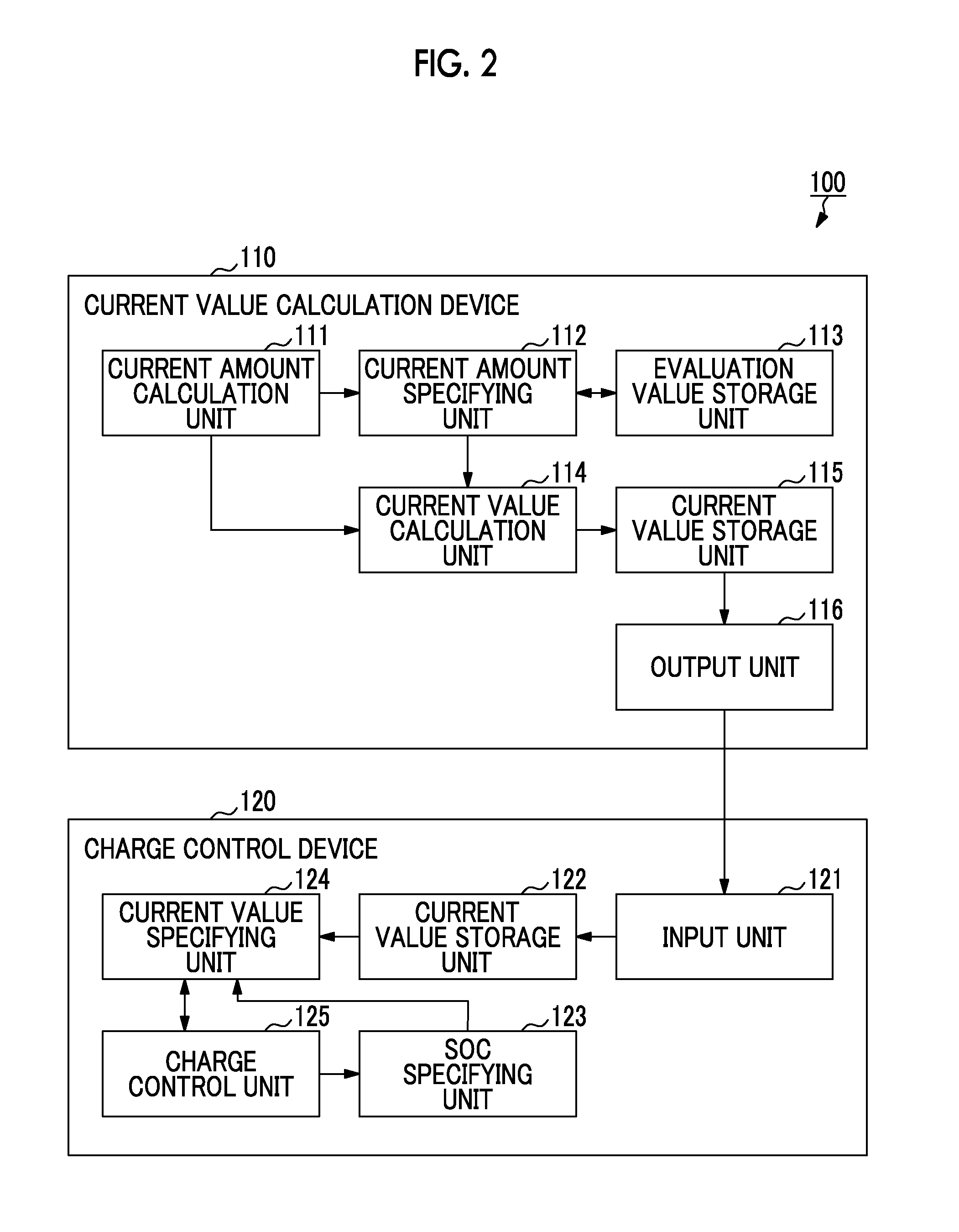
[0025]The charge control system 100 includes a current value calculation device 110 and a charge control device 120. The current value calculation device 110 calculates an appropriate current value in the charging of the secondary battery 210 for eac...

second embodiment

[0087]The current value calculation device 110 according to the first embodiment calculates a current value based on the worst conditions so as not to deviate from the operating range of the secondary battery 210. On the other hand, a current value calculation device 110 according to a second embodiment generates the relationship among the charging location, the SOC, and the current value for each state of the vehicle 200 or the secondary battery 210. As examples of the state of the vehicle 200 or the secondary battery 210, the number of passengers in the vehicle 200, power consumption of auxiliary devices (air conditioner, heater, and the like), the degree of deterioration of the secondary battery 210, and the like can be mentioned, for example. The current value specifying unit 124 of the charge control device 120 specifies the state of the vehicle 200 or the secondary battery 210 whenever the vehicle 200 arrives at the charging location. The current value specifying unit 124 spec...


PUM


Abstract

A charge control device determines a current value acquired by dividing a current amount that should be charged in a secondary battery in a vehicle at a charging location by an allowable charging time at the charging location on the basis of a charging amount as a physical quantity associated with the charging state of the secondary battery. When the vehicle arrives at the charging location, the charge control device allows a charging device provided at the charging location to charge the secondary battery with the current having the determined current value for the allowable charging time.

Description

RELATED APPLICATIONS[0001]The present application is National Phase of International Application No. PCT / JP2014 / 059015 filed Mar. 27, 2014, and claims priority from Japanese Application No. 2013-076388, filed Apr. 1, 2013, the disclosure of which is hereby incorporated by reference herein in its entirety.TECHNICAL FIELD[0002]The present invention relates to a charge control device, a charge control method, and a charge control system for controlling the charging of a secondary battery provided in a vehicle traveling on a path including a plurality of charging locations.BACKGROUND ART[0003]In recent years, the evaluation of electric vehicles has increased due to the growing awareness of environmental issues. Implementation of vehicles driven by a secondary battery is highly expected since it is possible to reduce the time and effort for wiring or maintenance and to eliminate the influence on the view due to the wiring.[0004]When introducing the secondary battery to the electric vehic...

Claims


Application Information

Patent Timeline
Patent Type & Authority Patents(United States)
IPC IPC(8): B60L11/18B60L3/00
CPCB60L11/1838B60L3/0046B60L11/1816B60L11/1861B60L2240/545B60L2240/547B60L2240/549B60L2240/80B60L2260/52B60L2260/54B60L2260/58Y02T10/705Y02T10/7005Y02T10/7044Y02T10/7072Y02T90/14B60L58/13Y02T10/70
Inventor MORITA, KATSUAKINIINOMI, TOSHIHIKOKONO, TAKAYUKIWAKASUGI, KAZUYUKIMOTOYAMA, HISASHISUZUKI, MASATO
Owner MITSUBISHI HEAVY IND ENG LTD
Learn More