Vehicle lamp

a technology for lamps and lampshades, applied in fixed installation, lighting and heating apparatus, transportation and packaging, etc., can solve the problems of increasing the depth size of the toroidal lens to some extent, and it is difficult to reduce the thickness of the lamp in the depth direction, so as to reduce the thickness of the lamp

Inactive Publication Date: 2016-10-04
KOITO MFG CO LTD
View PDF17 Cites 3 Cited by
  • Summary
  • Abstract
  • Description
  • Claims
  • Application Information

AI Technical Summary

Benefits of technology

[0009]To solve the above-mentioned problem, one or more embodiments of the present invention provides a vehicle lamp including a toroidal lens which can realize a reduction in thickness of the lamp.
[0026]As this occurs, in this lens, the cross section along the first plane is formed into the concave meniscus lens shape, and therefore, a depth dimension of the lens can be reduced, thereby making it possible to reduce the thickness of the resulting lamp.

Problems solved by technology

However, it is difficult to reduce the thickness of the lamp in depth direction because the toroidal lens is disposed so as to extend into the arc-like shape on the front side of the light source in the lamp, and therefore, a depth size of the toroidal lens has to be increased to some extent.

Method used


Image

  • Vehicle lamp
  • Vehicle lamp
  • Vehicle lamp

Examples


first embodiment

[0036]Firstly, the invention will be described.

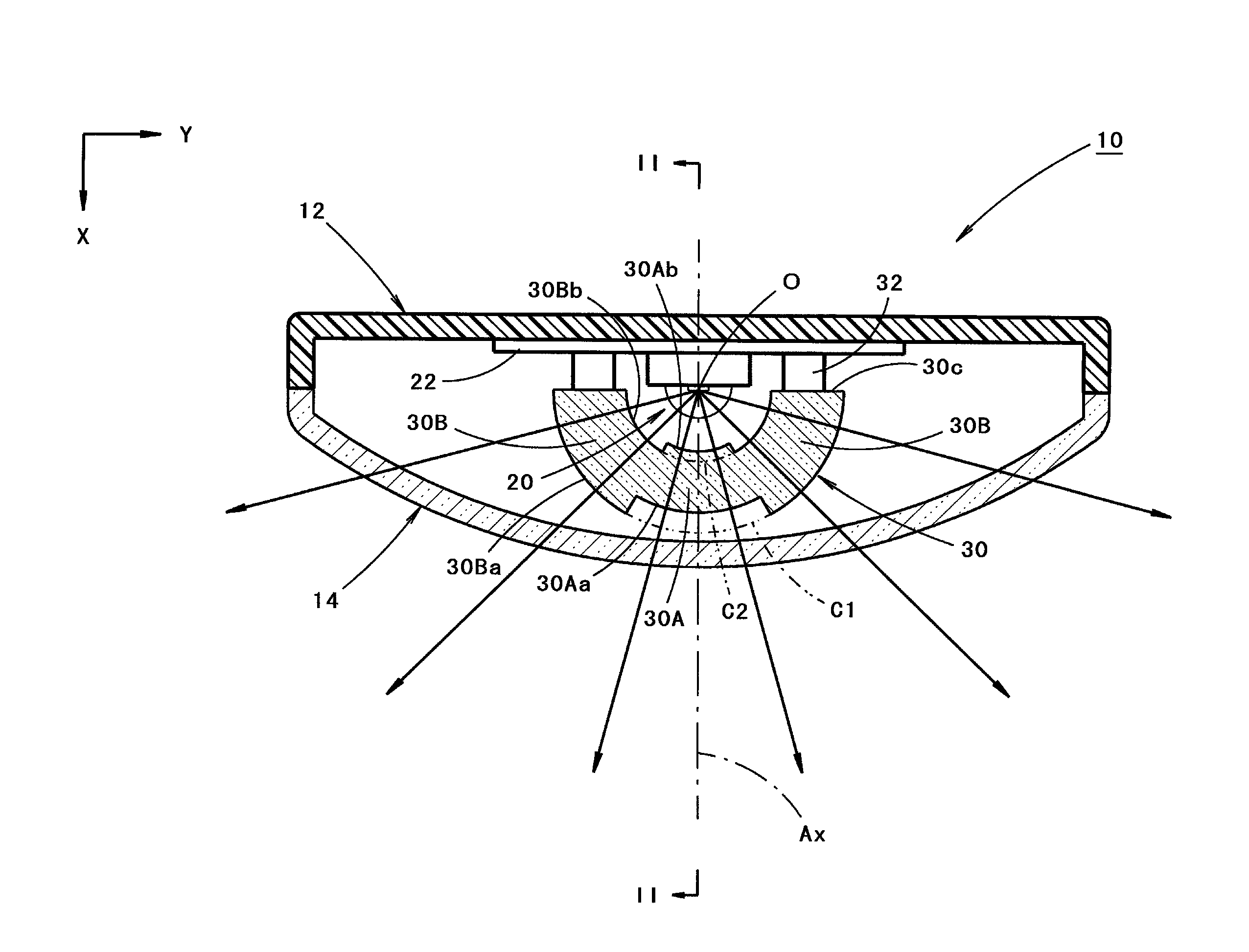
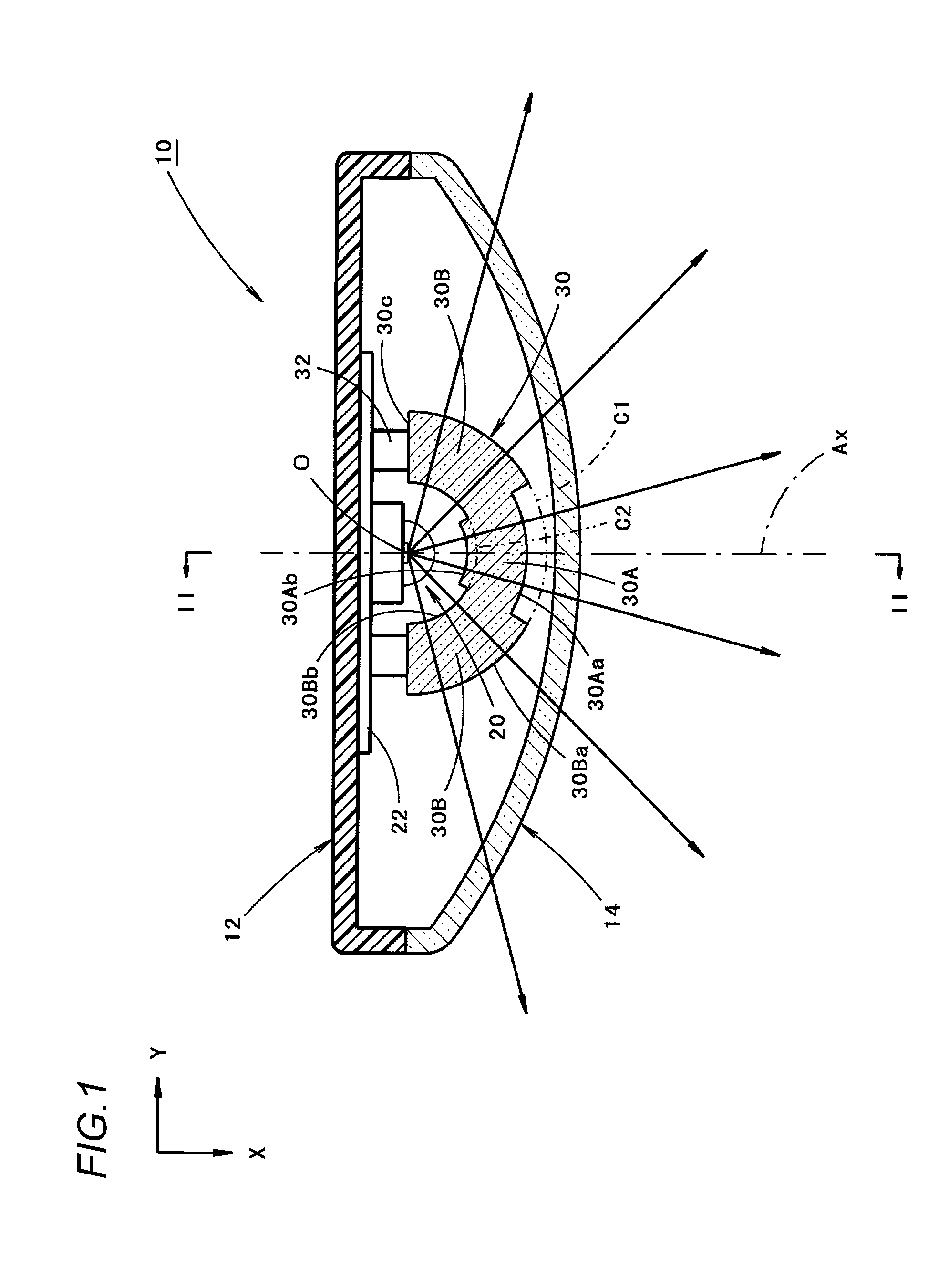
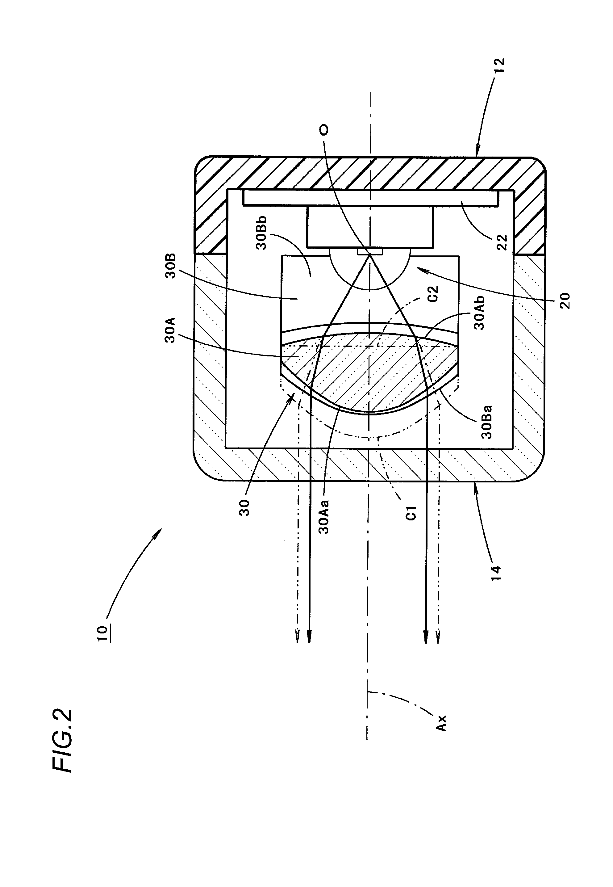
[0037]FIG. 1 is a sectional plan view showing a vehicle lamp 10 according to an embodiment of the invention. Additionally, FIG. 2 is a sectional view taken along the line II-II in FIG. 1.

[0038]As shown in these figures, the vehicle lamp 10 according to the embodiment is a tail lamp provided at a rear end portion of a vehicle. In this vehicle lamp 10, a light source 20 and a toroidal lens 30 are incorporated in a lamp compartment which is defined by a lamp body 12 and a transparent light transmitting cover 14 which is mounted at a front end opening of the lamp body 12.

[0039]It is noted that in this vehicle lamp 10, a direction indicated by an arrow X denotes a front (however at the “rear” of the vehicle) and a direction indicated by an arrow Y denotes a “rightward direction” which is at right angles to the “front” in FIG. 1.

[0040]The light source 20 is a red light emitting diode and is disposed with a light emitting surface thereof orien...

second embodiment

[0085]Next, the invention will be described.

[0086]FIG. 7 is a sectional plan view showing a main part of a vehicle lamp 310 according to this embodiment. Additionally, FIG. 8 is a sectional view taken along the line VIII-VIII in FIG. 7.

[0087]As shown in these figures, although a basic configuration of this embodiment is similar to that of the second modified example of the first embodiment, the second embodiment differs from the second modified example in that a lens 330 is disposed in place of the toroidal lens 30. Additionally, the configuration of a rear surface 340b of a light guiding plate 340 differs slightly from that of the second modified example.

[0088]Namely, the lens 330 of this embodiment is disposed so as to extend into an arc shape about a vertical line which passes through an illumination center O of a light source 20 and is supported on a light source support member 22 at a pair of left and right end faces 330c via a pair of left and right lens support members 32.

[00...


PUM


Abstract

A vehicle lamp is provided which includes a toroidal lens 30 which extends into an arc shape so as to surround a light source 20 from a front side thereof. By adopting this configuration, light emitted from the light source 20 is allowed to emanate from the toroidal lens 30 as it is as diffuse light in a horizontal plane in which the toroidal lens 30 extends, while the light is allowed to emanate from the toroidal lens 30 as parallel light in a vertical plane. Furthermore, a front surface 30Aa of a central portion 30A of the toroidal lens 30 in the direction in which the toroidal lens 30 extends into the arc shape is formed so as to be displaced rearwards relative to an imaginary extensional plane C1 from front surfaces 30Ba of general portions 30B which are situated at both sides of the central portion 30A.

Description

CROSS-REFERENCE TO RELATED APPLICATIONS[0001]The present application claims the benefit of priority of Japanese Patent Applications No. 2012-221421, filed on Oct. 3, 2012, and No. 2013-084327, filed on Apr. 12, 2013, which is incorporated herein by reference.BACKGROUND[0002]1. Field of the Invention[0003]Embodiments of the present invention relates to a vehicle lamp including a toroidal lens.[0004]2. Related Art[0005]A configuration of a vehicle lamp which has a toroidal lens which extends into an arc-like shape so as to surround a light source from a front side thereof, is disclosed in JP-A-S63-66801.[0006]Such the configuration of the vehicle lamp enables light emitted from the light source to emanate from the toroidal lens as it is as diffuse light in a first plane in which the toroidal lens extends. Further, such the configuration of the vehicle lamp enables the light to emanate as parallel light in a second plane which intersects the first plane at right angles.[0007]Therefore,...

Claims


Application Information

Patent Timeline
Patent Type & Authority Patents(United States)
IPC IPC(8): F21S8/10F21W107/10
CPCF21S48/2212F21S43/26
Inventor MOTOMURA, KENICHI
Owner KOITO MFG CO LTD
Why Eureka
Try Eureka