
Crank arm, crankset, and power measuring device for an at least partially human powered vehicle or training device with a crank drive

Active Publication Date: 2016-10-04
STORCK BICYCLE
View PDF7 Cites 21 Cited by
  • Summary
  • Abstract
  • Description
  • Claims
  • Application Information

AI Technical Summary

Benefits of technology

The patent connects carbon fiber plastics, which are commonly used in cycling, with a sensor. By using a lightweight material and not adding any additional components, the resulting crank arm is very light. In a preferred embodiment, the electronics unit is connected to the electric conductor by detachable contacts, which can be easily done with a plug and socket. This allows for easy customization and flexibility in installation.

Problems solved by technology

However, this is not to be understood as a restriction of the usability of the disclosure.
With the arrangement of the sensor in pockets of the crank arm, the problem arises that the crank arm must extensively be mechanically machined and is at the same time structurally weakened.
Furthermore, the sensor is not hidden from the user, which can adversely affect the look of the crank arm and is therefore not desired for design reasons.
With the arrangement on an inner surface of a hollow crank arm, the sensor can only be inserted and fixed with difficulties.
Sealing problems with the lead-through of the connection lines of the sensor out of the cavity result, and, in this case as well, the sensor is only partially protected against impacts from outside like, for instance, moisture accumulating in the cavity in the crank arm.
Furthermore, the weight of the crankset increases only insignificantly due to the integrated sensor, for instance only in the range of one-tenth of a percent.
In this way, additional wiring at the bicycle induced by the power measuring system, in particular wiring inside the bicycle frame, which would also be difficult to realize as the electronics unit in the bottom bracket shaft is rotating during the operation of the bicycle, becomes superfluous.
Such a merely calculative determination of the rotational frequency of the bottom bracket shaft requires, however, a sufficiently large computing power in the electronics unit and moreover is subject to a certain uncertainty.

Method used


Image

  • Crank arm, crankset, and power measuring device for an at least partially human powered vehicle or training device with a crank drive
  • Crank arm, crankset, and power measuring device for an at least partially human powered vehicle or training device with a crank drive
  • Crank arm, crankset, and power measuring device for an at least partially human powered vehicle or training device with a crank drive

Examples


Embodiment Construction

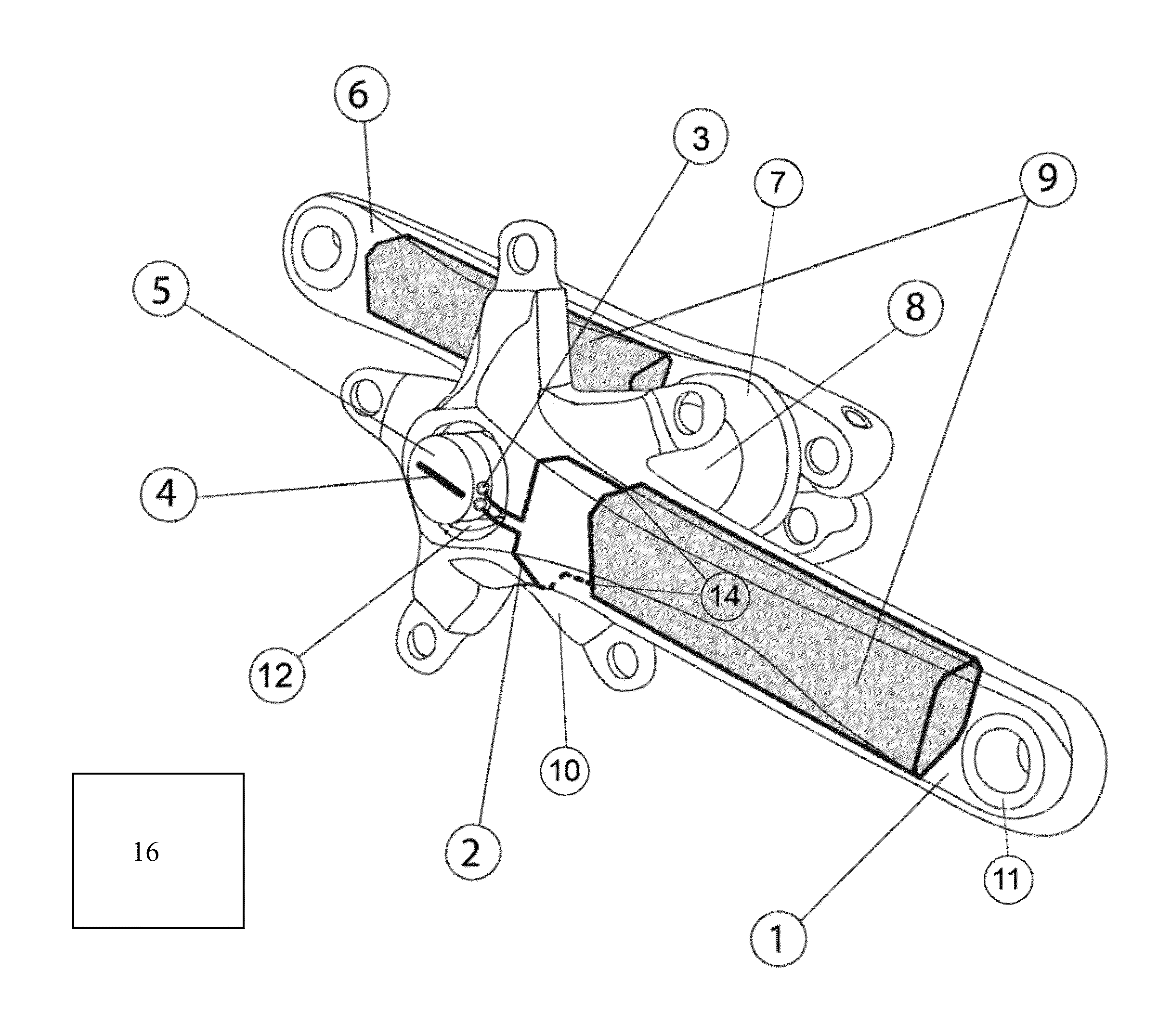
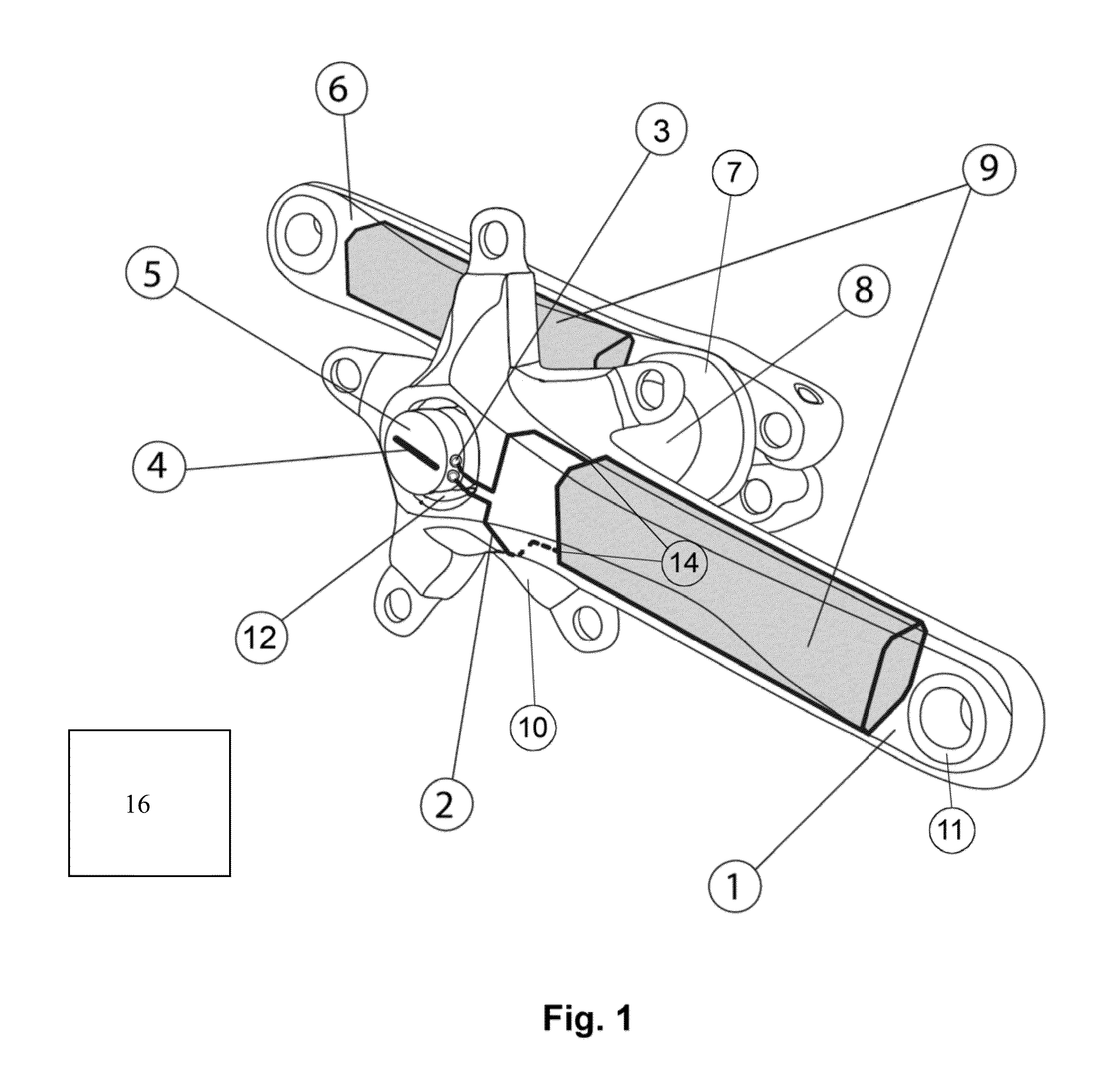
[0081]FIG. 1 shows a crankset according to the disclosure from in front obliquely from the right, viewed in the riding direction of the bicycle, with a right crank arm 1 and a left crank arm 6 in a horizontal position. The crank arms 1, 6 are connected by a bottom bracket shaft 8. Bottom bracket 7 is only indicated in the figure by an encapsulated ball bearing.

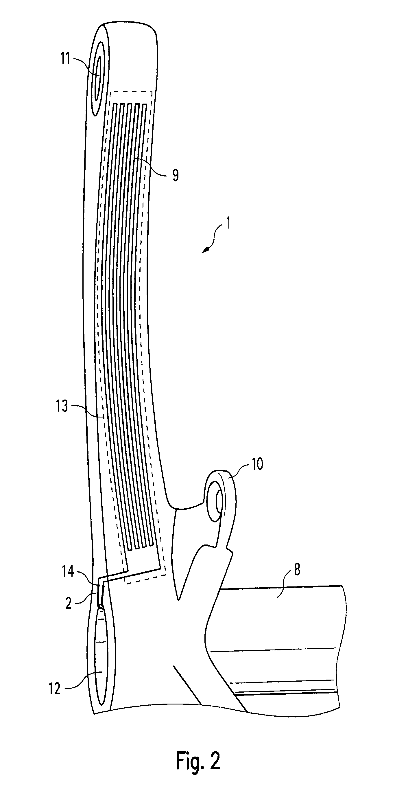
[0082]A crank spider 10 with five radial arms with bores arranged at their ends for fixing one or more chain wheels is integrally shaped to the end of right crank arm 1 near the bottom bracket. Right crank arm 1 is non-detachably connected to the right end of bottom bracket shaft 8, whereas left crank arm 6 is detachably connected to the left end of bottom bracket shaft 8 by means of a clamping.

[0083]The bodies of crank arms 1, 6 are made of carbon-fiber-reinforced plastics. Eyelets 11 made of aluminum with inner threads for screwing in the pedal axles are embedded in the ends of the two crank arms 1, 6 near the pedals.

[0084]A...


PUM


Abstract

A power measuring system for an at least partially human powered vehicle or training device with a crank drive, in particular a bicycle, with at least one crank arm of the bicycle being manufactured of fiber-reinforced plastics and the crank arm having a sensor, in particular a strain gage, and with the largest part of the sensor being directly enclosed on all sides by the fiber-reinforced plastics. The force exerted on the respective pedal and from this the torque exerted on the bottom bracket shaft is determined by an electronics unit, which is preferably arranged in a cavity in the bottom bracket shaft, from the signal of sensor. From this, together with the rotational frequency of bottom bracket shaft, which is possibly measured by further sensors or is determined in a calculative way, the power currently generated by the user of the bicycle is determined. The power values can, in particular wirelessly, be sent to a display unit and be displayed thereby in the form of power-related information. The sensors in both crank arms, make it possible to determine the power for the left and the right leg of the cyclist separately.

Description

BACKGROUND[0001]1. Field of the Disclosure[0002]The present disclosure relates to a crank arm, a crankset, and a power measuring device for an at least partially human powered vehicle or training device with a crank drive.[0003]2. Discussion of the Background Art[0004]By an at least partially human powered vehicle with a crank drive, we understand in particular a common bicycle with a foot pedal crank drive driven by the legs, but also any other at least partially human powered vehicle, in particular a road vehicle, a watercraft or an aircraft, in particular with one or more human powered wheels, which is completely or at least partially driven by the muscles of the user by means of a crank drive, i. e. the propulsion is generated by the rotation of the cranks.[0005]Examples for at least partially human powered vehicles with a crank drive which is not a foot pedal crank drive are bicycles with a hand crank drive, so-called handbikes.[0006]Examples for vehicles which are only partial...

Claims


Application Information

Patent Timeline
IPC IPC(8): G01L5/24G01L1/22G01L5/13B62M3/08G01L3/24G01L3/14A61B5/22
CPCB62M3/08G01L1/22G01L3/1457G01L5/13G01L3/242A61B5/221Y10T74/2168B62M3/00B62J45/414B62J45/421
Inventor HEINKEL, ULRICHWOLF, PETERKRIESTEN, DANIELODENWALD, STEPHANBUDER, JENS
Owner STORCK BICYCLE
Learn More