
128 Gigabit fibre channel physical architecture

a physical architecture and 128-gigabit fibre channel technology, applied in bus networks, digital transmission networks, data switching networks, etc., can solve the problems of limiting growth and deployment, high cost of those protocols being transferred, and at a very high cost, so as to achieve the effect of reducing cost or simplifying

Active Publication Date: 2016-10-04
AVAGO TECH INT SALES PTE LTD
View PDF8 Cites 8 Cited by
  • Summary
  • Abstract
  • Description
  • Claims
  • Application Information

AI Technical Summary

Benefits of technology

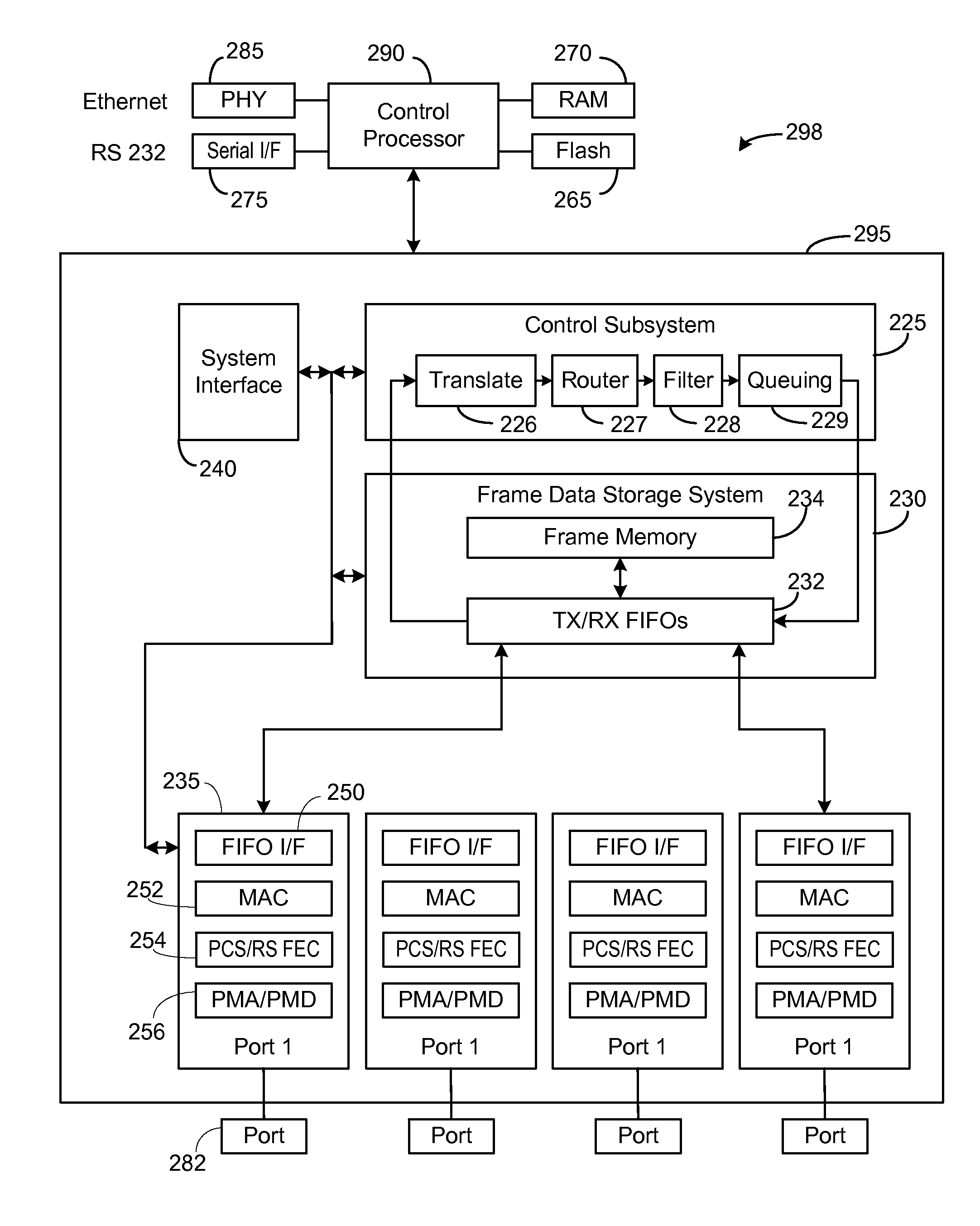
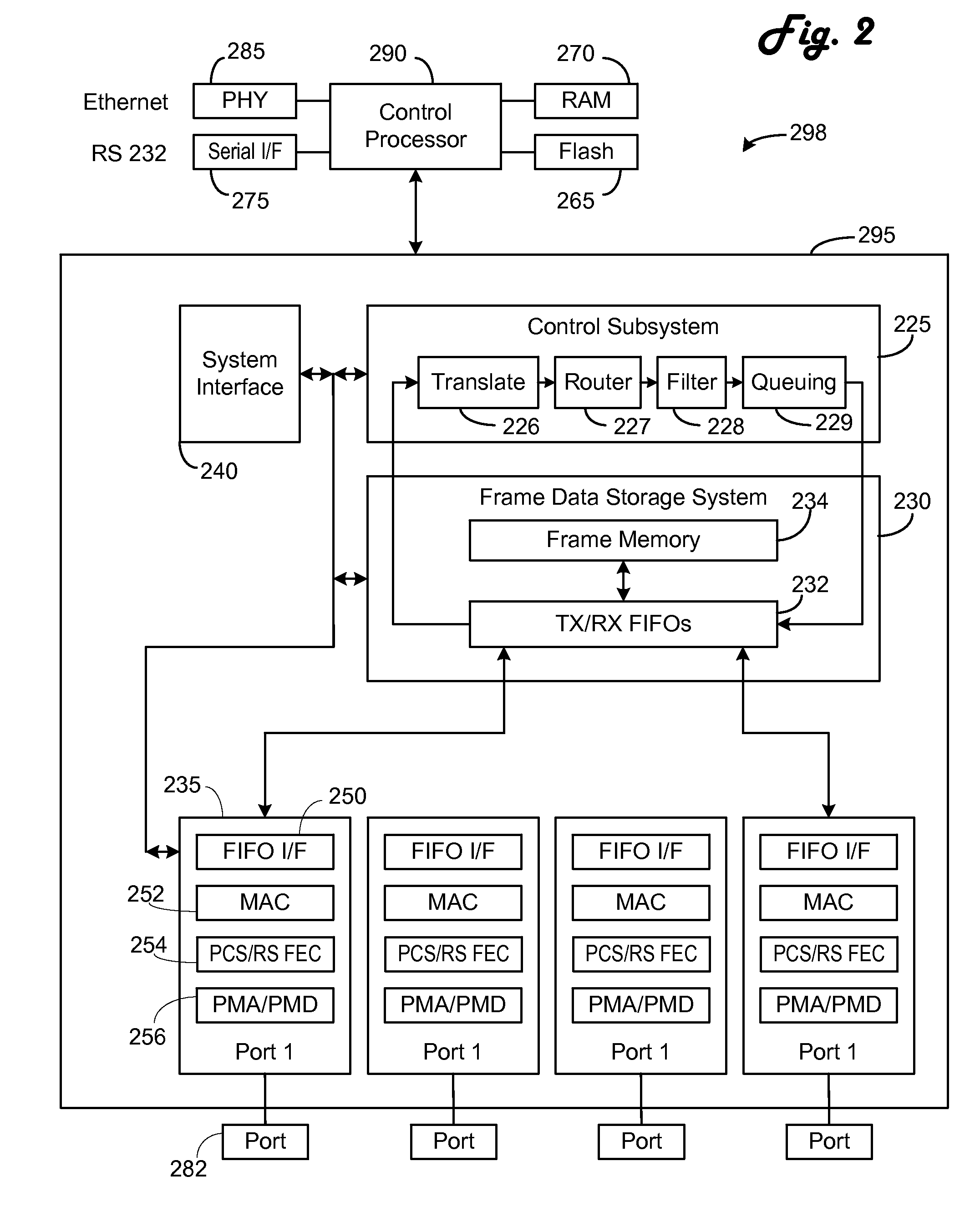
[0006]In the preferred embodiment of the present invention the PCS and FEC layers are combined into a single layer on a single chip and the number of lanes is set at four lanes. The combination allows removal of many modules as compared to a serial arrangement of a PCS layer and a Reed-Solomon FEC layer. The reduction in the number of lanes, as compared to 100 Gbps Ethernet, provides a further simplification or cost reduction by further reducing the needed gates of an ASIC to perform the functions. Changing the lanes in the FEC layer necessitates changing the alignment marker structure. In the preferred embodiment a lane zero marker is used as the first alignment marker in each lane to allow rapid sync. A second alignment marker indicating the particular lane follows the first alignment marker.

Problems solved by technology

Today Ethernet speeds of 40 and 100 Gigabits per second (Gbps) are available, though at a very high cost.
While elements could be used from 40 Gbps and 100 Gbps Ethernet, the use would raise concerns of the high cost of those protocols being transferred to the Fibre Channel variant, which would limit growth and deployment.

Method used


Image

  • 128 Gigabit fibre channel physical architecture
  • 128 Gigabit fibre channel physical architecture
  • 128 Gigabit fibre channel physical architecture

Examples


Embodiment Construction

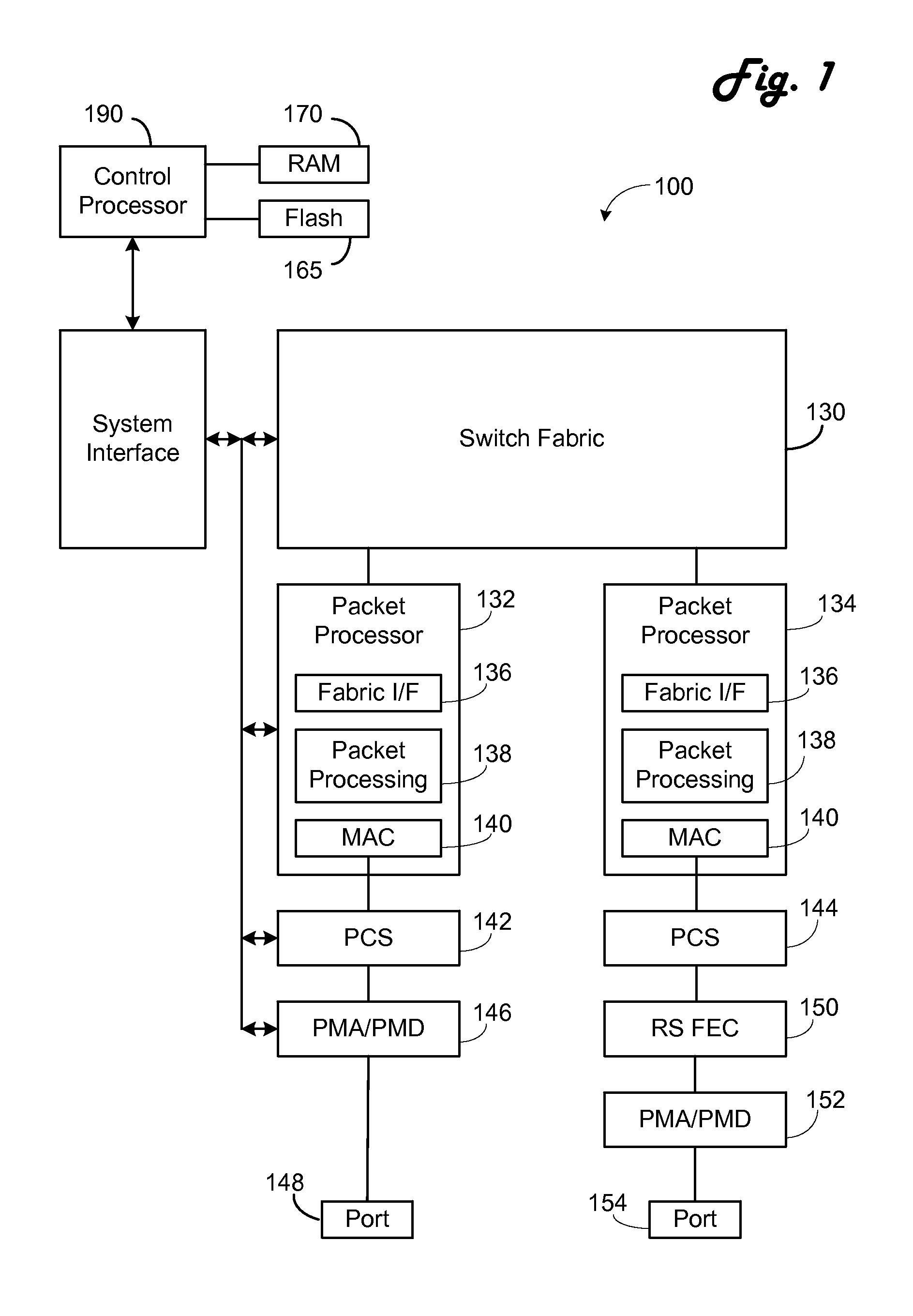
[0018]Referring now to FIG. 1, an exemplary Ethernet switch 100 is shown. A switch fabric 130 forms the basic switching matrix. Connected to the switch fabric 130 are a 40 Gbps packet processor 132 and a 100 Gbps packet processor 134. Each packet processor 132 and 134 includes a fabric interface 136 connected to the switch fabric 130. Each packet processor 132, 134 includes a packet processing module 138 which performs conventional packet analysis and processing functions. Each packet processor 132, 134 also includes a media access control (MAC) module 140. Network data passes through the fabric interface 136, packet processing module 138 and MAC module 140 in series in the transmit direction and in the inverse order in the receive direction.

[0019]A PCS module 142 is connected to the 40 Gbps packet processor 132 while a PCS module 144 is connected to the 100 Gbps packet processor 134. A physical medium attachment (PMA) and physical medium dependent (PMD) module 146 is connected betw...


PUM


Abstract

The PCS and FEC layers are combined into a single layer and the number of lanes is set at four lanes. The combination allows removal of many modules as compared to a serial arrangement of a PCS layer and an FEC layer. The reduction in the number of lanes, as compared to 100 Gbps Ethernet, provides a further simplification or cost reduction by further reducing the needed gates of an ASIC to perform the functions. Changing the lanes in the FEC layer necessitates changing the alignment marker structure. In the preferred embodiment a lane zero marker is used as the first alignment marker in each lane to allow rapid sync. A second alignment marker indicating the particular lane follows the first alignment marker.

Description

CROSS REFERENCE TO RELATED APPLICATIONS[0001]This application claims the benefit under 35 U.S.C. §119(e) of U.S. Provisional Patent Application Ser. Nos. 61 / 839,349 entitled “128Gb FCp Architecture,” filed Jun. 25, 2013; 61 / 862,451 entitled “128Gb FCP Architecture,” filed Aug. 5, 2013; 61 / 863,309 entitled “128G FCP Architecture,” filed Aug. 7, 2013; 61 / 880,017 entitled “128GFCP Architecture,” filed Sep. 19, 2013; 61 / 886,750 entitled “128GFCp Architecture,” filed Oct. 4, 2013; and 61 / 909,042 entitled “128GFC Speed Negotiation Topics,” filed Nov. 26, 2013, which are all hereby incorporated by reference.BACKGROUND OF THE INVENTION[0002]1. Field of the Invention[0003]The invention relates to the physical layer of high speed networking.[0004]2. Description of the Related Art[0005]Speeds of network links are ever increasing. Today Ethernet speeds of 40 and 100 Gigabits per second (Gbps) are available, though at a very high cost. Fibre Channel speeds of 16 Gbps are available and 32 Gbps de...

Claims


Application Information

Patent Timeline
Patent Type & Authority Patents(United States)
IPC IPC(8): H04L12/931H04L12/935H04L12/24H04L12/40H04B10/40H04L49/111
CPCH04L49/357H04L49/30H04L49/40H04B10/40H04L12/4013H04L41/0681H04L49/352H04L69/321
Inventor MEHTA, ANILKIPP, SCOTT
Owner AVAGO TECH INT SALES PTE LTD
Learn More