Travel beverage container

a beverage container and travel technology, applied in drinking containers, transportation and packaging, locking devices, etc., can solve the problems of not being able to close the drink aperture, the area between the seal mechanism and the lid is difficult to clean properly, and the drink stopper is not able to do so

Active Publication Date: 2016-10-11
THE COLEMAN CO INC
View PDF206 Cites 51 Cited by
  • Summary
  • Abstract
  • Description
  • Claims
  • Application Information

AI Technical Summary

Benefits of technology

[0005]According to one embodiment, the disclosed subject technology relates to a lid for a beverage container having a drop-down seal assembly for easy cleaning of the seal assembly and the associated drink apertures, but where the seal assembly is not disassembled or removed from the lid during conversion from the use position to the cleaning position, and wherein the seal assembly is operated by a trigger assembly that is pushed radially inwardly in a direction transverse to a longitudinal axis of the beverage container.
[0006]The disclosed subject technology further relates to a lid having a lock connected to the lid housing. The lock prevents engagement of the seal assembly by the trigger assembly even when the seal assembly is in the operable position.
[0012]The disclosed subject technology further relates to a seal assembly wherein a portion of the hinge member extends beyond a thread ring of the lid housing when the seal assembly is in the cleaning position, i.e., radially exterior of the thread ring, to assist in preventing the lid assembly from being connected to the container member when the seal assembly is in the cleaning position.

Problems solved by technology

While such beverage containers and seal mechanisms according to the prior art provide a number of advantages, they nevertheless have certain limitations.
Further, the area between the seals associated with the seal mechanism and the lid, and other components of the seal mechanism and trigger mechanism are difficult to properly clean, especially in a dishwasher environment.
Further, the drink stopper is not capable of closing the drink aperture in the second position.
Further, the drink stopper cannot be operated by the trigger member when the seal assembly is in the second position.

Method used


Image

  • Travel beverage container
  • Travel beverage container
  • Travel beverage container

Examples


Embodiment Construction

[0034]While the travel beverage container discussed herein is susceptible of embodiments in many different forms, there is shown in the drawings and will herein be described in detail preferred embodiments of the invention with the understanding that the present disclosure is to be considered as an exemplification of the principles of the invention and is not intended to limit the broad aspect of the invention to the embodiments illustrated.

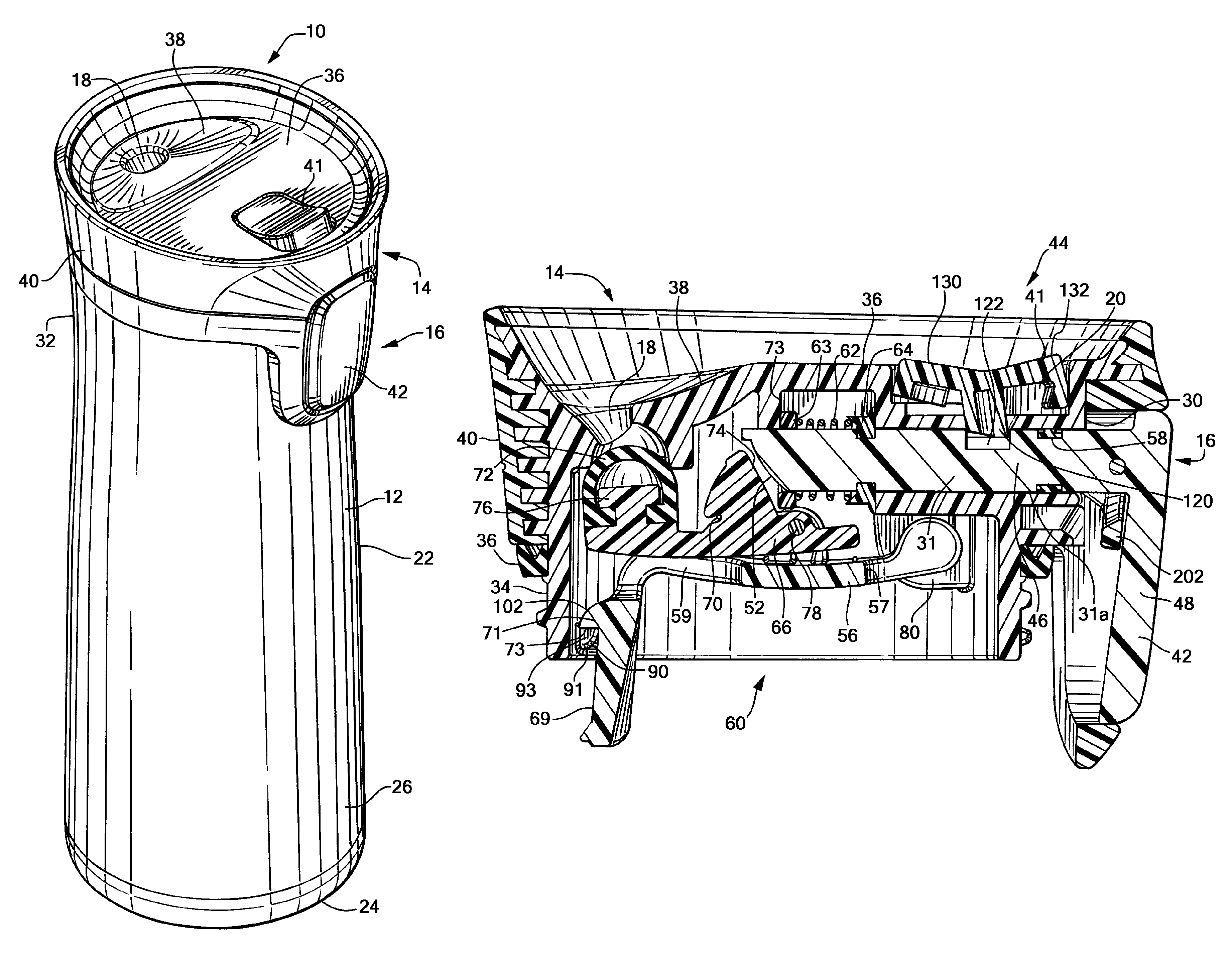
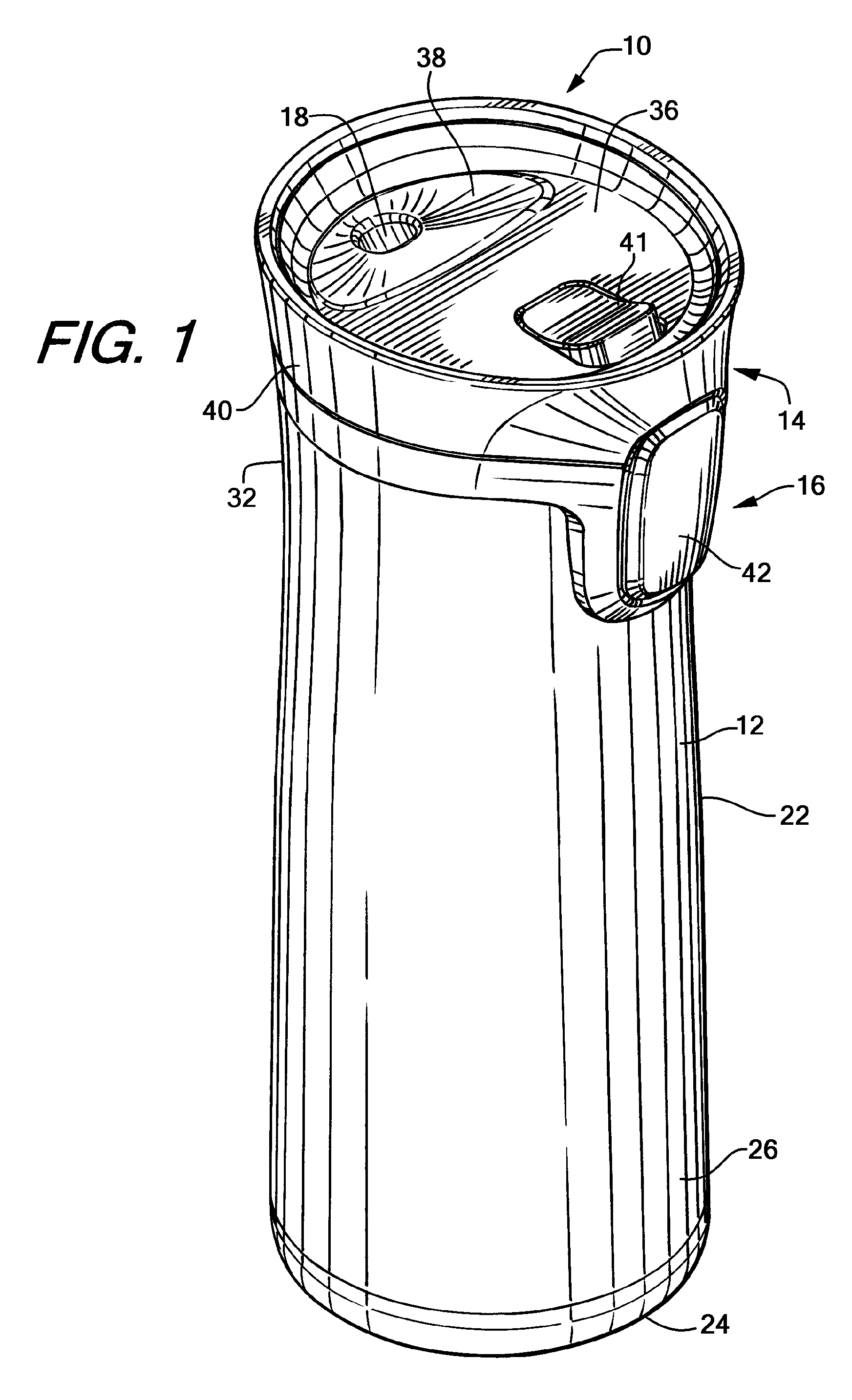
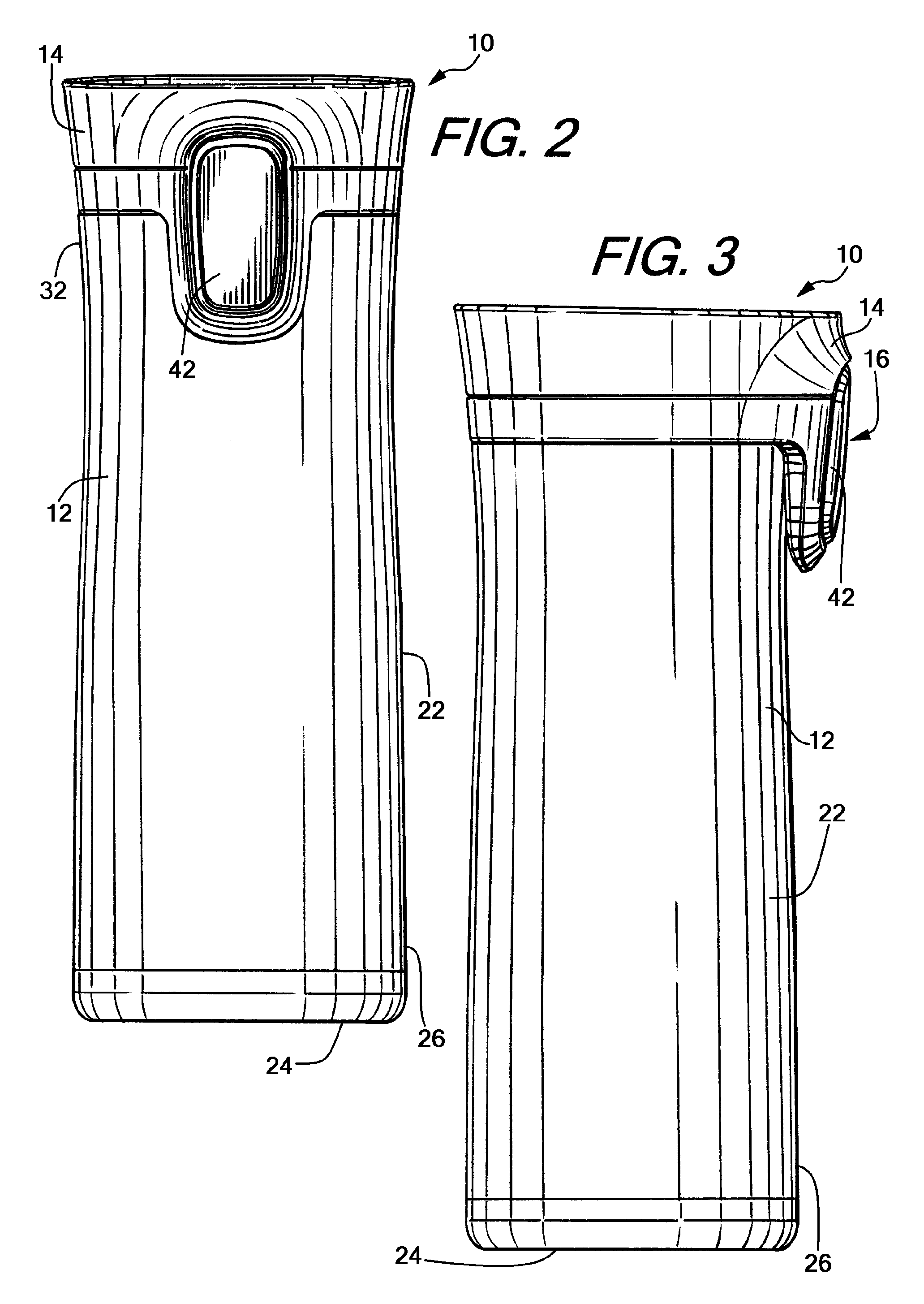
[0035]Referring now to the figures, and specifically to FIGS. 1-9, there is shown a beverage container 10 generally comprising a container body 12 and a lid assembly 14. The lid assembly 14 has a trigger mechanism 16 that operates to open and close a drinking aperture 18 in the lid assembly 14. Additionally, the trigger mechanism 16 also preferably operates to open and close a vent aperture 20 to allow pressure residing within the container body 12 to be initially released through the vent aperture 20 as opposed to the drink aperture 18. In a pre...


PUM


Abstract

A cleanable lid assembly is provided for a beverage container. The lid assembly has a lid housing having a drink aperture, and a seal assembly that is connected to the lid housing while movable between a first or operable position and a second or cleaning position. The seal assembly has a stopper that can open and close the drink aperture in the first position. The seal assembly is pivotally connected to the lid housing to transition to the cleaning position. A locking member extends transversely from the seal assembly to engage a stop on the lid housing and lock the seal assembly in the operable position. The locking member is moveable radially inward to disengage from the stop and to allow the seal assembly to transition from the first position to the cleaning position.

Description

CROSS-REFERENCE TO RELATED APPLICATIONS[0001]This application claims priority to U.S. Provisional Patent Application No. 61 / 873,084, filed Sep. 3, 2013, which is incorporated herein by reference in its entirety and made a part hereof.FEDERALLY SPONSORED RESEARCH OR DEVELOPMENT[0002]Not Applicable.TECHNICAL FIELD[0003]The present invention relates generally to a beverage container, and more specifically to a travel beverage container with a cleanable and lockable seal assembly.BACKGROUND OF THE INVENTION[0004]Beverage containers and seal mechanisms for beverage containers are well known in the art. Traditionally, seal mechanisms are located in the lid of the beverage container and are secured in a fixed location in the lid adjacent the various openings in the lid housing. While such beverage containers and seal mechanisms according to the prior art provide a number of advantages, they nevertheless have certain limitations. For example, debris may be retained between certain component...

Claims


Application Information

Patent Timeline
Patent Type & Authority Patents(United States)
IPC IPC(8): A47G19/22B65D43/26A45F3/18B65D43/02
CPCA47G19/2272A45F3/18B65D43/265B65D43/0225B65D2251/0003B65D2251/20B65D41/28B65D43/16B65D43/26B65D51/1672B65D51/18B65D55/02B65D2251/0015B65D2251/0021B65D2251/0028B65D2251/0078B65D2251/0081B65D2251/009B65D2543/00046
Inventor COON, ROBERTHURLEY, PAUL
Owner THE COLEMAN CO INC
Why Eureka
Try Eureka