Air blowing system and image forming apparatus including same

a blowing system and air technology, applied in the field of air blowing system and image forming apparatus, can solve the problems of disturbing users, whistling sound, unwanted noise, etc., and achieve the effect of reducing unwanted nois

Active Publication Date: 2016-10-11
SHARP KK
View PDF5 Cites 1 Cited by
  • Summary
  • Abstract
  • Description
  • Claims
  • Application Information

AI Technical Summary

Benefits of technology

[0020]The inventors of the present invention have found that in an air blowing system including: an air blowing device; and a duct that guides air blown by the air blowing device, the periodical bending of the duct that occurs when the air blown by the air blowing device passes through the duct can be reduced progressively with a reduction in the surface area of the continuous face on the surface of the duct, and the reduced periodical bending of the duct can efficiently prevent the vibration of the duct and the resonance of the duct that could be caused by the vibration.
[0030]The present invention can reduce unwanted noise during air blowing (specifically, a whistling sound produced when the air blown by the air blowing device passes through the ventilation section and a resonating sound produced by the duct bending periodically (vibrating), and hence resonating, when the air blown by the air blowing device passes through the duct).

Problems solved by technology

Air blowing systems including an air blowing device and a duct that guides air blown by the air blowing device have disadvantages related to unwanted noise produced by the air flow as detailed below.
The air blown by the air blowing device, when it passes through the ventilation section in the air blowing system, produces an unpleasant whistling sound, disturbing the user.
The vibration in turn causes resonance and produces an unpleasant resonating sound, disturbing the user.
The duct and ribs of Japanese Patent Application Publication, Tokukai, No. 2001-166622, however, are not sufficiently capable of reducing the whistling sound produced when the air blown by the air blowing device passes through the ventilation section, because the air paths are separated simply by ribs.
The simple separation of air paths by ribs of Japanese Patent Application Publication, Tokukai, No. 2001-166622 is also not sufficiently capable of reducing the resonating sound produced by the resonance of the duct that bends periodically (vibrates) when the air blown by the air blowing device passes through the duct.

Method used


Image

  • Air blowing system and image forming apparatus including same
  • Air blowing system and image forming apparatus including same
  • Air blowing system and image forming apparatus including same

Examples


first embodiment

[0073]FIG. 3 is an oblique view of the rear side of the air blowing system 200 in accordance with the first embodiment as viewed obliquely from below. FIG. 4 is an oblique view of the front side of the air blowing system 200 in accordance with the first embodiment as viewed obliquely from below. FIG. 5 is a plan view of the air blowing system 200 in accordance with the first embodiment. FIG. 6 is a bottom view of the air blowing system 200 in accordance with the first embodiment. FIG. 7 is a front view of the air blowing system 200 in accordance with the first embodiment. FIG. 8 is a rear view of the air blowing system 200 in accordance with the first embodiment. FIG. 9 is a left side view of the air blowing system 200 in accordance with the first embodiment. FIG. 10 is an oblique view of the rear side of the air blowing system 200 in accordance with the first embodiment as viewed from the left, with an air blowing device 210 and a second duct cover member 234 for a downstream duct ...

second embodiment

Ribs in Downstream Duct

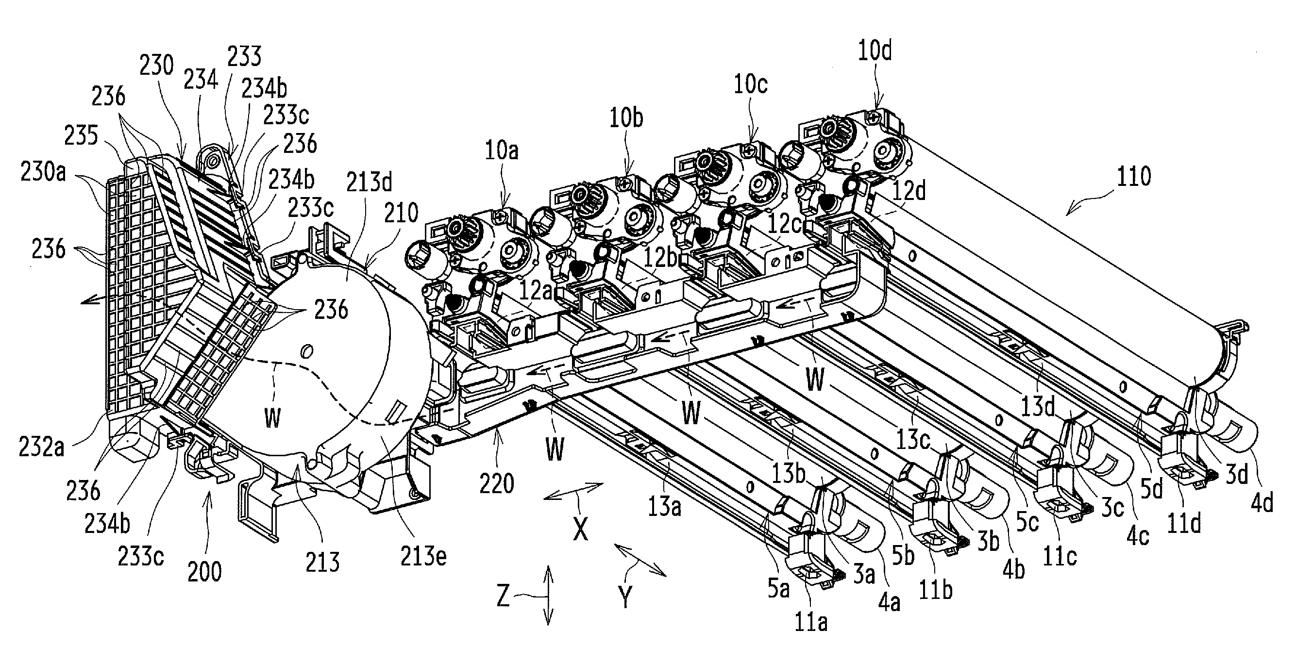
[0120]FIG. 19 is an oblique view of the rear side of the air blowing system 200 in accordance with the second embodiment as viewed from the left, with the air blowing device 210 and the second duct cover member 234 for the downstream duct 230 being removed. FIG. 20 is an oblique view of the rear side of the air blowing system 200 in accordance with the second embodiment as viewed slightly obliquely from above, with the second duct cover member 234 for the downstream duct 230 and the filter 112b being removed. FIG. 19 depicts the air blowing system 200 being attached to the charging units 5a to 5d in the photosensitive body units 10a to 10d.

[0121]As illustrated in FIGS. 19 and 20, the downstream duct 230 has an inner surface on which there are provided deflecting ribs 233d serving as ribs that deflect the air W blown by the air blowing device 210 in a deflecting direction different from the air blowing direction. More specifically, the deflecting direction is ...

third embodiment

Distorted Portion

[0125]In the preceding embodiments the distorted portion 235 is a concave distortion where a part of the inner wall face 234a is distorted in a concave shape, which is by no means intended to be limiting the invention. Additionally or alternatively, the distorted portion 235 may be a convex distortion where a part of the inner wall face 234a is distorted in a convex shape.

[0126]FIG. 21 is a schematic cross-sectional view of an example of the downstream duct 230 having as the distorted portion 235 a convex distortion where a part of the inner wall face 234a is distorted in a convex shape.

[0127]The distorted portion 235, being a convex distortion where a part of the inner wall face 234a is distorted in a convex shape, blocks the passageway of air W. The distorted portion 235, being a convex distortion, has at least a wall face 235c (235c1) that is farthest from the ventilation section 112 and perpendicular or substantially perpendicular to the air blowing direction of...


PUM


Abstract

Disclosed is an air blowing system including: an air blowing device; a duct that guides air blown by the air blowing device; and a ventilation section disposed downstream of the duct in terms of an air blowing direction in which air is blown by the air blowing device so that the air blown by the air blowing device strikes and passes through the ventilation section, wherein the duct has a distorted portion where a part of an inner wall face of the duct located between the air blowing device and the ventilation section is distorted perpendicular or substantially perpendicular to the air blowing direction so that the air blown by the air blowing device flows perpendicularly or substantially perpendicularly to the air blowing direction. Also disclosed is an air blowing system including: an air blowing device; and a duct that guides air blown by the air blowing device, wherein the duct has an outer surface on at least a part of which there is provided a surface area reducing portion for reducing a surface area of a continuous face.

Description

CROSS-REFERENCE TO RELATED APPLICATIONS[0001]The present application hereby claims priority under 35 U.S.C. §119(a) on Japanese Patent Applications, Tokugan, Nos. 2014-137104 and 2014-137105 (both filed Jul. 2, 2014 in Japan), the entire contents of which are hereby incorporated herein by reference.BACKGROUND OF INVENTION[0002]The present invention relates in general to an air blowing system including an air blowing device and a duct that guides air blown by the air blowing device and relates in particular to an air blowing system included in a copying machine, a multi-function device, a printer, or any other like image forming apparatus that forms an image on a recording sheet, for example, by an electrophotographic image forming method.[0003]Air blowing systems including an air blowing device and a duct that guides air blown by the air blowing device have disadvantages related to unwanted noise produced by the air flow as detailed below.[0004]For example, a ventilation section is ...

Claims


Application Information

Patent Timeline
Patent Type & Authority Patents(United States)
IPC IPC(8): G03G21/20
CPCG03G21/206
Inventor HATANAKA, MASATSUGUMORITA, KIWAMUYAMANAKA, HISASHI
Owner SHARP KK
Why Eureka
Try Eureka