
Lighting system and a method for determining the energy consumption of a lighting system

a lighting system and energy consumption technology, applied in the field of lighting system and energy consumption determination of lighting system, can solve the problems of increasing number of presets and difficulty in keeping in mind what buttons on the user interface of the lighting system do, and achieve the effect of improving the creation of lighting scenes or programs

Active Publication Date: 2016-10-11
SIGNIFY HLDG BV
View PDF15 Cites 0 Cited by
  • Summary
  • Abstract
  • Description
  • Claims
  • Application Information

AI Technical Summary

Benefits of technology

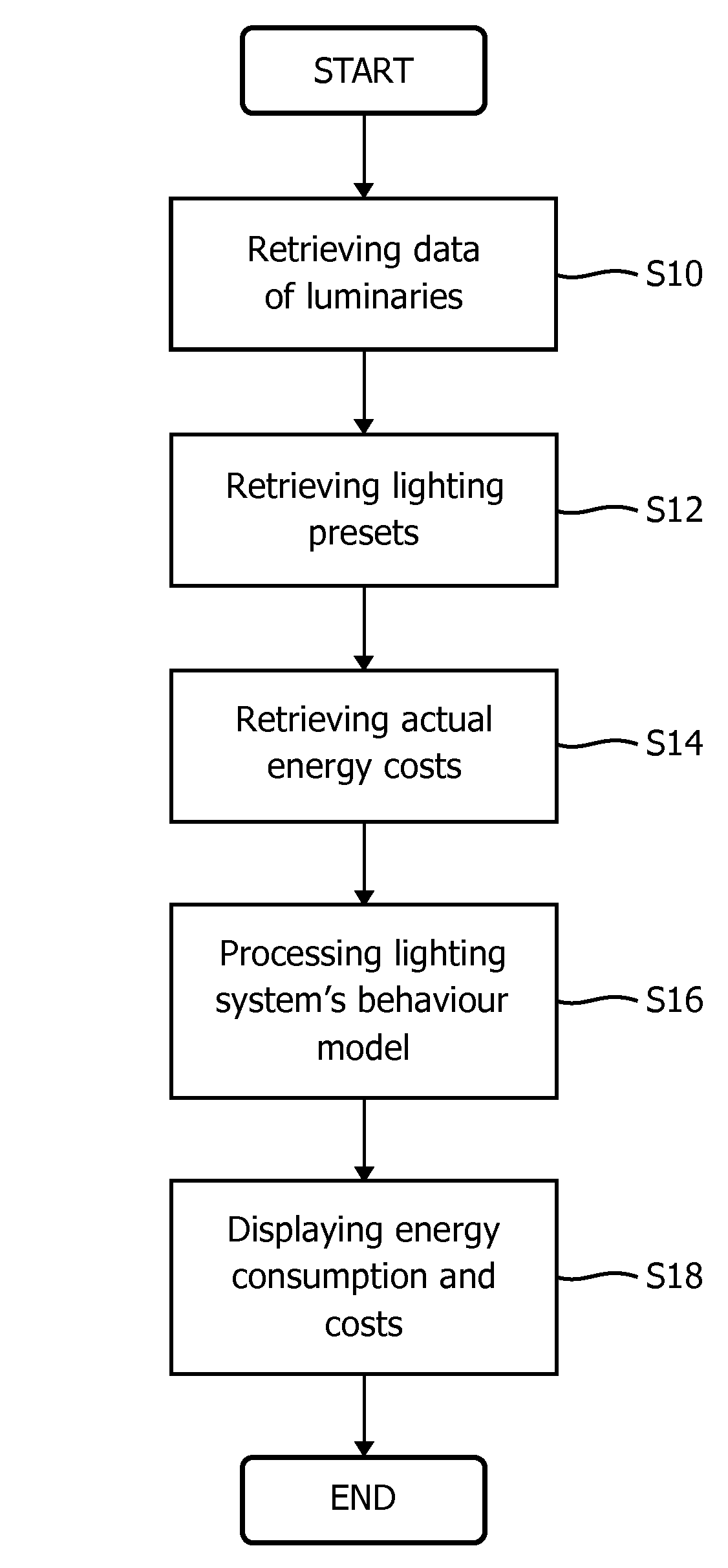
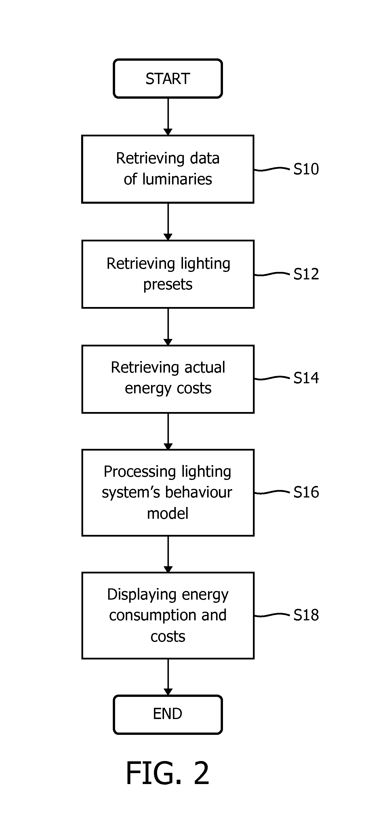
[0010]a calculation module being adapted to calculate the energy consumption of the lighting system based on a lighting scene to be created depending on data retrieved from the first and the second database. This allows to calculate the energy consumption for each lighting scene to be created, thus allowing to improve the creation of lighting scenes with regard to energy.
[0020]the calculation module is further adapted to calculate overall energy costs of a lighting scene to be created based on the calculated energy consumption and the energy costs retrieved from the third database. Thus, also the energy costs may be taken into account, which may make the selection of a lighting scene creation by a user more comfortable.
[0023]The lighting scene selector module may be further adapted to automatically create a lighting program from the automatically selected lighting scenes. This enables a user also to set an energy target for a lighting program, for example for a program for one month and to meet given energy consumption or cost targets.

Problems solved by technology

With the increasing opportunities with new control systems for lighting systems the number of offered presets is growing, so keeping in mind what buttons on a user interface of a lighting system do what becomes increasingly tricky.

Method used


Image

  • Lighting system and a method for determining the energy consumption of a lighting system
  • Lighting system and a method for determining the energy consumption of a lighting system
  • Lighting system and a method for determining the energy consumption of a lighting system

Examples


Embodiment Construction

[0044]In the following, functionally similar or identical elements may have the same reference numerals. The terms “light”, “lighting unit” and “luminairy” relate in the following to the same.

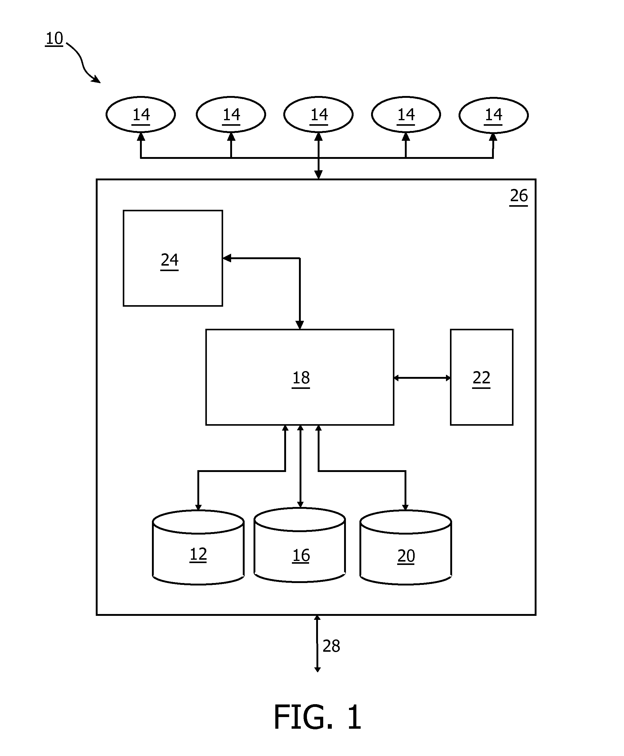
[0045]FIG. 1 shows a lighting system 10 with several luminaries 14. Operation of the luminaries 14 can be controlled, for example the lighting color, the dimming level, the saturation. The luminaries 14 may contain several color LEDs (Light Emitting Diodes) for generating a colored lighting. For controlling the luminaries 14, a central lighting controller 26 is provided, which may be implemented by a standard Personal Computer (PC), which is configured by a program implementing control functionality of the luminaries, or a lighting controller comprising a processor or microcontroller, which are also configured by a program to implement the control functionality for the luminaries. The central lighting controller 26 can control one, several or all luminaries by transmitting control commands to t...


PUM


Abstract

The invention relates to the creation of lighting programs or scenes with a lighting system taking energy consumption into account. An embodiment of the invention provides a lighting system (10) comprising—a first database (12) containing data of the luminairies (14) of the lighting system, —a second database (16) containing information for lighting presets of the luminairies of the lighting system for a lighting scene to be created, and—a calculation module (18) being adapted to calculate the energy consumption of the lighting system based on a lighting scene to be created depending on data retrieved from the first and the second database.

Description

FIELD OF THE INVENTION[0001]The invention relates to the creation of lighting programs or scenes with a lighting system taking energy consumption into account.BACKGROUND OF THE INVENTION[0002]Modern lighting systems enable users to set different lighting scenes, such as selecting a preferred lighting color or a dynamic lighting. Lighting scenes may be created by professional lighting designers, or by users themselves. A lighting scene comprises presets of the lamps to render the desired lighting scene. Users may control a lighting system by selecting a desired lighting scene to be rendered by means of a user interface. Several lighting scenes can be combined to a lighting program like a playlist. Users may then select a certain lighting program fitting their individual lighting wishes[0003]With the increasing opportunities with new control systems for lighting systems the number of offered presets is growing, so keeping in mind what buttons on a user interface of a lighting system d...

Claims


Application Information

Patent Timeline
Patent Type & Authority Patents(United States)
IPC IPC(8): G05F1/00H05B37/02H05B39/04H05B41/36
CPCH05B37/029H05B47/155H05B47/19H05B45/10H05B45/20Y02B20/40
Inventor SOROKIN, MIKHAIL VICTOROVICHTIELENS, JOHANNA CORNELIA MARIA FRANCISCA
Owner SIGNIFY HLDG BV
Learn More