Clamping of media items

a technology for media items and clamping, applied in the direction of instruments, atm details, apparatus for dispensing discrete articles, etc., can solve the problems of failure of certain operations, inability to meet the other modes of operation, and the compression force applied to a bunch of media items

Active Publication Date: 2016-10-18
NCR CORP
View PDF16 Cites 0 Cited by
  • Summary
  • Abstract
  • Description
  • Claims
  • Application Information

AI Technical Summary

Benefits of technology

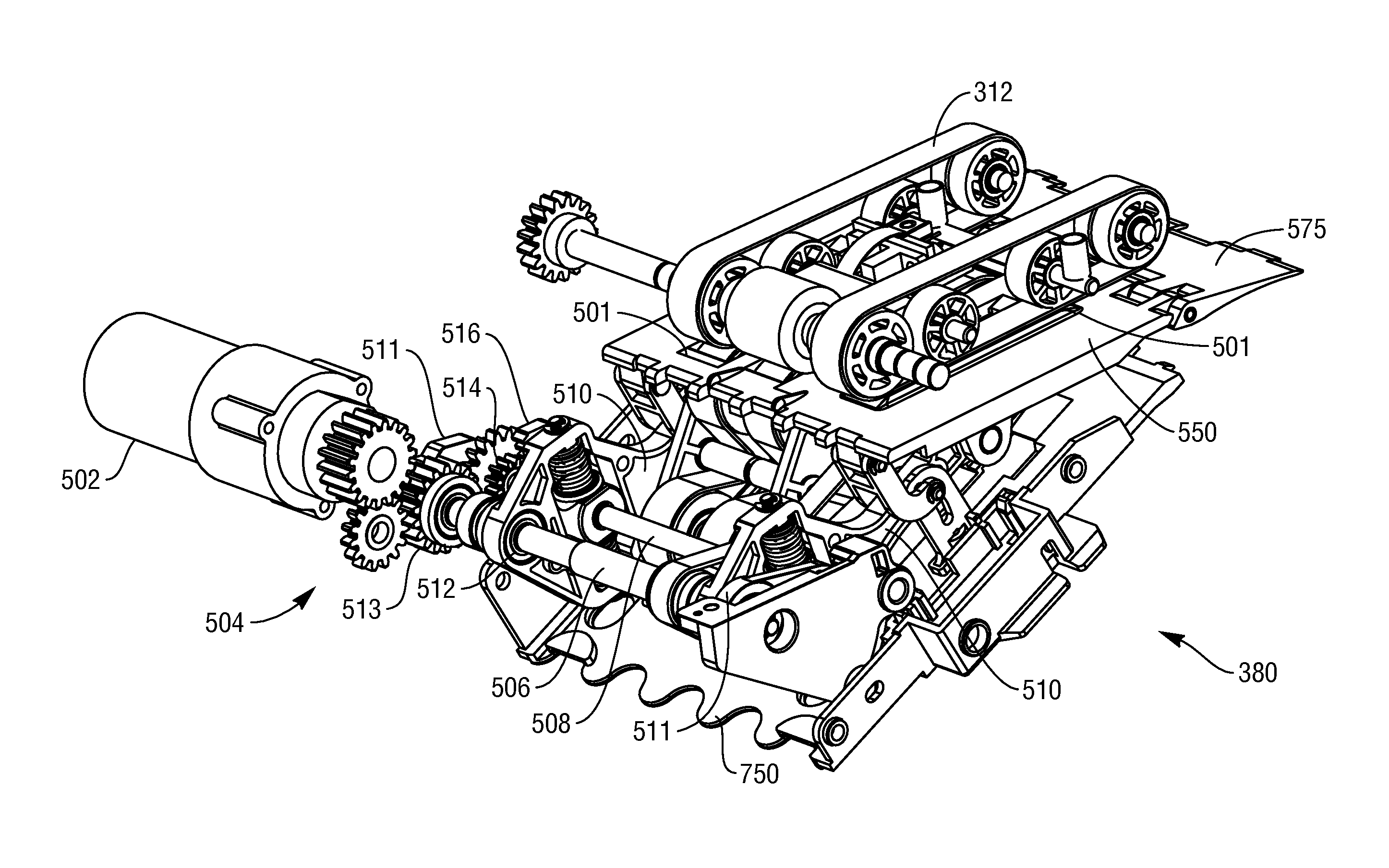
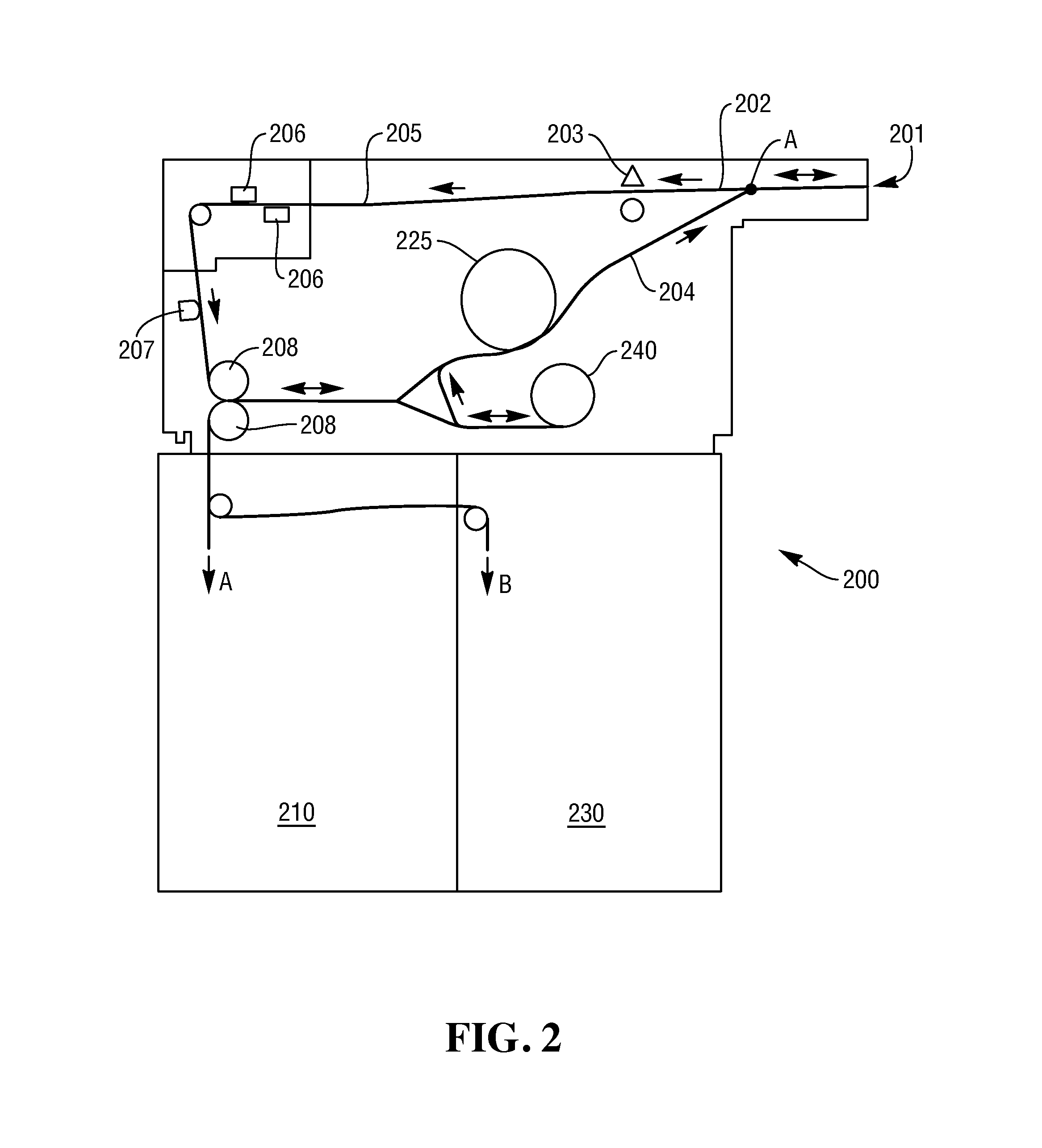
[0006]It is an aim of certain embodiments of the present invention to provide a method and apparatus for effectively transporting a bunch of media items along at least one transport path within an SST.
[0007]It is an aim of certain embodiments of the present invention to provide a method and apparatus for effectively removing or adding a media item from / to a bunch of media items.
[0010]It is an aim of certain embodiments of the present invention to provide a method and apparatus for applying a predetermined clamp force to a bunch of media items in an accurate and repeatable manner without adversely affecting bunch feeding / picking / separation operations.
[0027]removing or adding a media item from or to the bunch of media items to respectively decrease or increase said thickness of the bunch of media items and moving the clamp surface to maintain the predetermined clamp force as the thickness is decreased or increased.
[0060]Certain embodiments of the present invention provide a method of clamping a bunch of media items between a clamp surface and a support surface, wherein an orientation of the clamp surface relative to the support surface is automatically controlled to be substantially constant during selected movements of the clamp surface towards or away from the support surface. In turn, an accurate and repeatable document pressure control apparatus is provided without adversely affecting bunch feeding, picking and / or separation operations.

Problems solved by technology

However, in certain modes of operation of an SST, a compression force applied to a bunch of media items may not be suitable for all other modes of operation, such as when separating a media item from a bunch of media items.
This can cause failure during certain operations at the SST.

Method used


Image

  • Clamping of media items
  • Clamping of media items
  • Clamping of media items

Examples


Embodiment Construction

[0074]In the drawings like reference numerals refer to like parts.

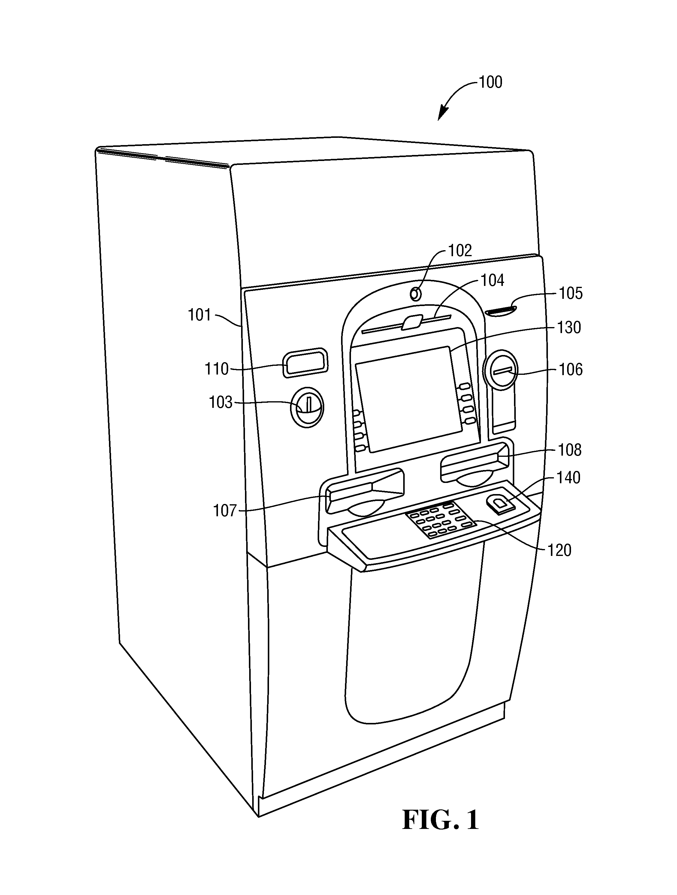
[0075]FIG. 1 illustrates a self-service check depositing terminal in the form of an image-based check depositing Automated Teller Machine (ATM) 100. It will be appreciated that certain embodiments of the present invention are applicable to a wide variety of terminals in which items of media such as checks and / or currency notes and / or giros and / or lottery tickets and / or other such flexible sheet-like items of media are to be transported and directed in different directions. The type of terminal will of course be appropriate for the type of items of media being transported.

[0076]As illustrated in FIG. 1, the ATM 100 includes a fascia 101 coupled to a chassis (not shown). The fascia 101 defines an aperture 102 through which a camera (not shown) images a customer of the ATM 100. The fascia 101 also defines a number of slots for receiving and dispensing media items and a tray 103 into which coins can be dispensed. The slot...


PUM

PropertyMeasurementUnit
angleaaaaaaaaaa
angleaaaaaaaaaa
clamp forceaaaaaaaaaa

Abstract

The present invention provides apparatus and a method for transporting at least one media item along a transport path, comprising locating a bunch of media items between at least one support surface and at least one clamp surface, and selectively moving said clamp surface towards or away from said support surface to apply a predetermined clamp force to the bunch of media items, wherein a predetermined angle of said clamp surface relative to said support surface is substantially constant when said clamp surface is moved towards or away from said support surface.

Description

FIELD OF THE INVENTION[0001]The present invention relates to a method and apparatus for transporting media items along a transport path. In particular, but not exclusively, the present invention relates to transporting media items, such as currency notes, checks, or the like, along a transport path within a media item processing module and clamping the media items with a desired force at a predetermined location on the transport path while the media item processing module is in a predetermined mode of operation.[0002]Various situations are known in which media items are transported along a transport pathway in a Self-Service Terminal (SST). For example, in a typical check depositing Automated Teller Machine (ATM), an ATM customer is allowed to deposit a check (without having to place a check in the deposit envelope) in a publically accessible, unattended environment. To deposit a check, the ATM customer inserts an identification card through a card slot of the ATM, enters the amount...

Claims


Application Information

Patent Timeline
Patent Type & Authority Patents(United States)
IPC IPC(8): G07F1/04G07D13/00G07F11/04G07F7/04G07F19/00G07D11/00
CPCG07D13/00G07D11/0003G07D11/0018G07D11/0021G07D11/0024G07D11/0027G07D11/0033G07F7/04G07F11/045G07F19/00G07F19/202G07F19/205B65H2301/4314B65H2403/942B65H2404/63B65H2701/182B65H2701/1912B65H31/3027G07D11/10G07D11/14G07D11/16G07D11/17G07D11/18G07D11/165
Inventor ROXAS, JOSEPHGRANADEROS, CARLO
Owner NCR CORP
Why Eureka
Try Eureka