Control for optically aligning an X-ray tube and X-ray detector

a control device and x-ray tube technology, applied in the field of medical imaging system, can solve problems such as obstructing some space around the patient, and achieve the effects of reducing the occupied space near the patient, reducing the weight and bulkiness of the x-ray imaging device, and being easy to move and position

Active Publication Date: 2016-10-25
KONINKLIJKE PHILIPS ELECTRONICS NV
View PDF17 Cites 3 Cited by
  • Summary
  • Abstract
  • Description
  • Claims
  • Application Information

AI Technical Summary

Benefits of technology

[0007]In trauma environments, it may be favorable to reduce the weight and bulkiness of an X-ray imaging device to make the device easier to move and to position and, further on, to reduce the occupied space near the patient. An X-ray imaging device having a foldable mechanical link between an X-ray source and a detector may obstruct some space around the patient.
[0008]Also, it may be favorable to modify or control a distance between an X-ray tube and a detector more individually for increasing the available space at the patient whenever it is necessary.
[0009]Therefore, there may exist a need for a less bulky X-ray imaging device that is easier to move and to position as commonly known X-ray trauma devices allowing free exposures when necessary and with less space obstruction.

Problems solved by technology

An X-ray imaging device having a foldable mechanical link between an X-ray source and a detector may obstruct some space around the patient.

Method used


Image

  • Control for optically aligning an X-ray tube and X-ray detector
  • Control for optically aligning an X-ray tube and X-ray detector
  • Control for optically aligning an X-ray tube and X-ray detector

Examples


Embodiment Construction

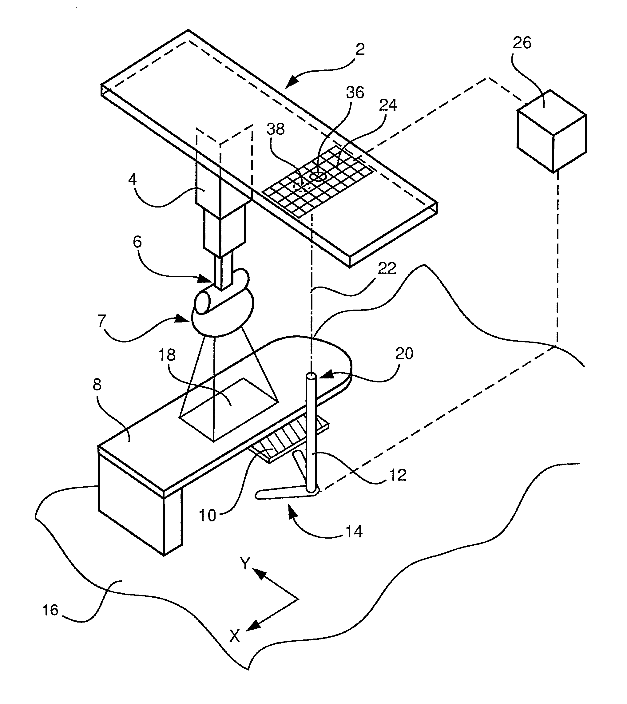
[0043]FIG. 1 shows an overview of the system according to the invention. A ceiling suspension 2 supports an X-ray tube arm 4 and comprises at least one actuating / drive means for moving the X-ray tube arm 4 along the ceiling in X- and Y-direction. The tube arm 4 itself holds the X-ray tube 6 adapted for emitting X-ray beams to a patient trolley 8 present below the X-ray tube. The patient trolley 8 itself does not constitute a part of the system according to the invention and is merely displayed for illustration purposes.

[0044]A detector 10 is mounted to a detector trolley 12, which detector trolley has a base 14 movable in X- and Y-direction on the floor 16. The detector 10 can thereby be moved under the trauma trolley 8 and thereby move into and out of a region of interest 18.

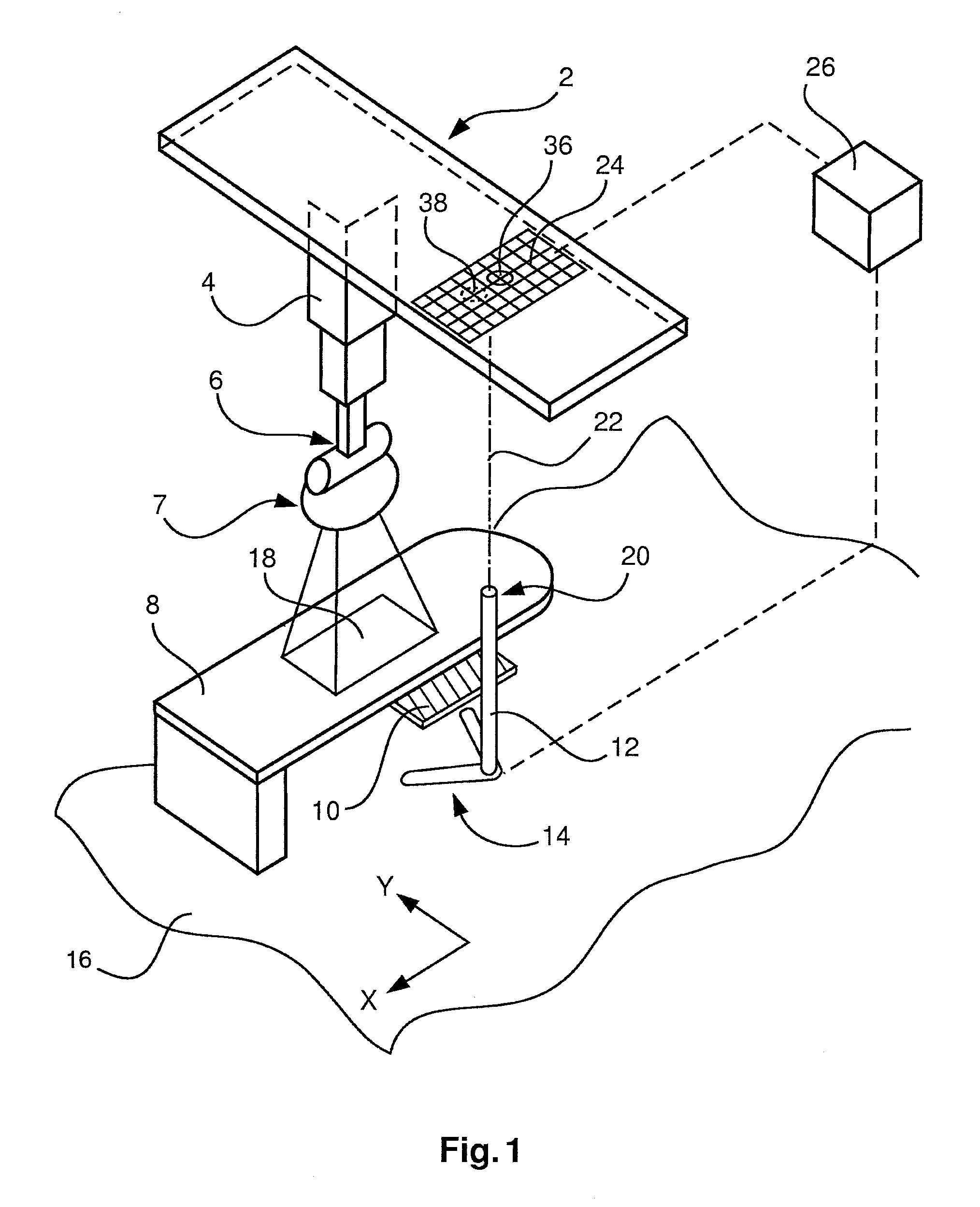
[0045]For attaching or linking the position of the detector 10 to the position of the X-ray tube 6, an optical indication unit 20 is fixedly mounted on the detector trolley 12 for emitting an optical indication...


PUM


Abstract

An X-ray imaging system includes an X-ray tube (6), a ceiling suspension (2) for the X-ray tube, a detector trolley (12) with an X-ray detector (10) mounted thereon, an active sensor matrix (24), an optical indication unit (20) and a control unit (26). The active sensor matrix (24) is fixedly mounted on the ceiling suspension (2), the optical indication unit (20) is fixedly mounted to the detector trolley (12) and is adapted for emitting an optical indication (22) onto the active sensor matrix (24). The control unit (26) is connected to the active sensor matrix (24) and is adapted for acquiring the position of the optical indication (22) on the active sensor matrix (24) and to create control signals for aligning the detector trolley position and the ceiling suspension position relative to each other.

Description

CROSS-REFERENCE TO PRIOR APPLICATIONS[0001]This application is the U.S. National Phase application under 35 U.S.C. §371 of International Application No. PCT / 1B2012 / 056716, filed on Nov. 26, 2011, which claims the benefit of U.S. Provisional Patent Application No. 61 / 565,545, filed on Dec. 1, 2011. These applications are hereby incorporated by reference herein.FIELD OF THE INVENTION[0002]The present invention relates to a medical imaging system and a method for providing an x-ray image.BACKGROUND OF THE INVENTION[0003]For trauma x-ray application, technicians usually have to bring a detector and an X-ray tube near a patient lying on a trauma trolley in an environment with a lot of people around. A patient may be wired to medical equipment that may disturb a proper X-ray examination. Therefore, trauma X-ray applications are sophisticated.[0004]Usually, for an X-ray examination in this environment, there are two general different workflows existing, depending on the size, shape and pos...

Claims


Application Information

Patent Timeline
Patent Type & Authority Patents(United States)
IPC IPC(8): A61B6/08A61N5/10H01J37/22G02B7/00A61B6/04A61B6/00G02B27/64H04B10/00
CPCA61B6/587A61B6/0492A61B6/08A61B6/4405A61B6/461A61B6/547A61N5/1049G02B7/005G02B27/64H01J37/22A61B6/4411A61B6/4452A61B6/4464A61B6/585A61B6/588A61N2005/105A61N2005/1051H01J2237/1501H01J2237/20292H01J2237/2482H01J2237/24528H04B10/22H04B10/11
Inventor KURZE, CHRISTOPH
Owner KONINKLIJKE PHILIPS ELECTRONICS NV
Why Eureka
Try Eureka