Intravascular arterial to venous anastomosis and tissue welding catheter

a technology of intravascular arterial and venous anastomosis, which is applied in the field of intravascular arterial to venous anastomosis and tissue welding catheter, can solve the problems of clotting of veins or arteries, restricting operations, etc., and achieves consistent and repeatable fistula creation, the effect of reducing operating tim

Active Publication Date: 2016-10-25
AVENU MEDICAL
View PDF84 Cites 12 Cited by
  • Summary
  • Abstract
  • Description
  • Claims
  • Application Information

AI Technical Summary

Benefits of technology

[0012]The present disclosed invention eliminates the above described open procedures, reduces operating time, and allows for a consistent and repeatable fistula creation.
[0015]The inventive catheter-based devices track over a guidewire which has been placed from a first vessel, such as a vein, into a second vessel, such as an artery, or more broadly between any other two vascular structures. The distal tip of the catheter has a tapered shape which allows the catheter to advance and dilate easily through the vessel walls. Proximal to the distal tip, the catheter has a significant reduction in diameter, and then a blunt, oval shaped tapered surface. As the catheter is further advanced, the blunt proximal surface comes into contact with the wall of the first vessel and encounters resistance, and cannot perforate through the wall into the second vessel. The distal tip, which has a matching blunt surface on its proximal end, is then retracted, capturing the walls of the two vessels between the two blunt surfaces. A known, controlled pressure (approximately 100 mN / mm2-400 mN / mm2) is applied between the two surfaces. The pressure can be controlled either internally in the catheter or by the handle attached to the proximal end of the catheter. Heat energy is then applied to the blunt surfaces for approximately 1-30 seconds to weld the walls of the two vessels together. It is possible to apply heat energy to only one surface as well. Heat energy can be applied through several different methods, including, but not limited to, RF, DC resistance, inductance, or a combination thereof. The heat energy is controlled at a known temperature ranging from between about 150-300 C. The heat may be applied by applying a steady energy, pulsing energy, incrementing energy, decrementing energy, or a combination thereof.

Problems solved by technology

Such procedures are time consuming, clinician dependent (open to surgical error), and often result in strictures, or clotting of the vein or artery.

Method used


Image

  • Intravascular arterial to venous anastomosis and tissue welding catheter
  • Intravascular arterial to venous anastomosis and tissue welding catheter
  • Intravascular arterial to venous anastomosis and tissue welding catheter

Examples


Embodiment Construction

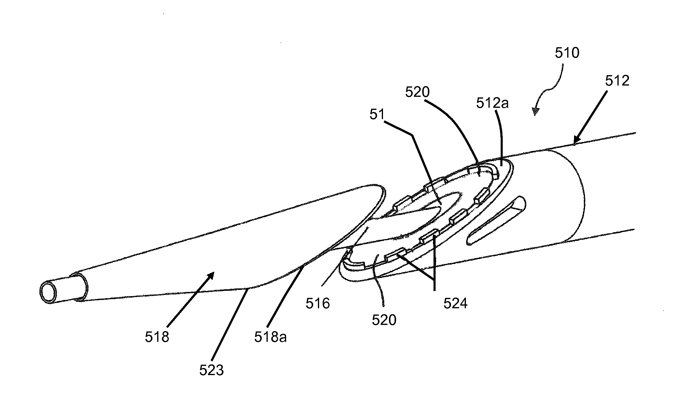
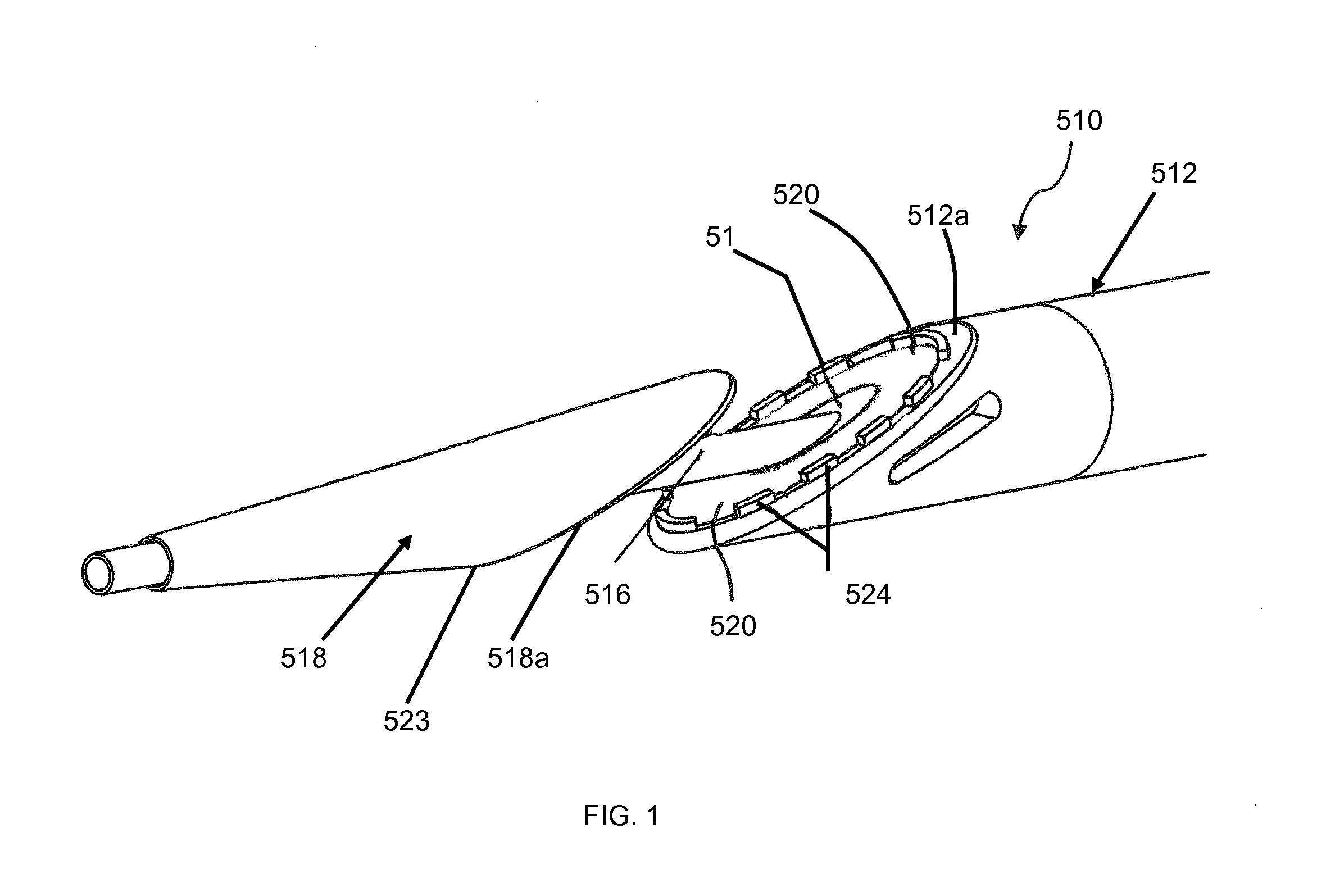
[0039]Referring now more particularly to the drawings, as illustrated in FIG. 1, a DC resistive heat catheter 510 is shown, which comprises an elongate outer tube 512 having an outer diameter that can range from 3F-12F. It may be manufactured from a variety of materials, either polymeric or metallic. It comprises a central lumen 514, into which a tubular structure 516, which defines its own lumen, disposed on a tip 518, may slidably engage. There are separate lumens that run down the elongated core of the outer tube 512 for wiring heating elements 520, 522 (proximal and distal as shown in FIG. 1 and FIG. 11 respectively), disposed on aligned blunt tapered faces 512a and 518a, respectively, of the respective elongate outer tube 512 and distal tip 518, and to measure the temperature during the coaptation and cutting processes.

[0040]In the operation of this configuration, the catheter may be powered using DC resistive energy to the active proximal heat transfer element 520 with the dis...


PUM

PropertyMeasurementUnit
temperatureaaaaaaaaaa
pressureaaaaaaaaaa
temperatureaaaaaaaaaa

Abstract

A catheter-based device tracks over a guidewire which has been placed from a first blood vessel into a second blood vessel. The distal tip of the catheter is advanced into the second vessel while a proximal member remains in the first vessel. Matching blunt tapered surfaces on each of the distal tip and the proximal member are clamped together, with adjacent walls of each vessel between them, after which a known, controlled pressure is applied between the two surfaces. Heat energy is then applied to the blunt surfaces for approximately 1-30 seconds to weld the walls of the two vessels together. After coaptation of the vessel walls, the heat is increased to then cut through the vessel walls to create a fistula of the desired size.

Description

[0001]This application claims the benefit under 35 U.S.C. 119(e) of the filing date of Provisional U.S. application Ser. No. 61 / 596,670, entitled Intravascular Arterial to Venous Anastomosis and Tissue Welding Catheter, filed on Feb. 8, 2012, and is also related to U.S. application Ser. No. 13 / 161,356, entitled Intravascular Arterial to Venous Anastomosis and Tissue Welding Cathete, filed on Jun. 15, 2011. Both of these prior applications are expressly incorporated herein by reference, in their entirety.BACKGROUND OF THE INVENTION[0002]In the body, various fluids are transported through conduits throughout the organism to perform various essential functions. Blood vessels, arteries, veins, and capillaries carry blood throughout the body, carrying nutrients and waste products to different organs and tissues for processing. Bile ducts carry bile from the liver to the duodenum. Ureters carry urine from the kidneys to the bladder. The intestines carry nutrients and waste products from t...

Claims


Application Information

Patent Timeline
Patent Type & Authority Patents(United States)
IPC IPC(8): A61B18/04A61B18/08A61B18/14A61B17/11A61B18/00
CPCA61B18/04A61B17/11A61B18/1492A61B18/082A61B2017/1107A61B2017/1139A61B2018/0013A61B2018/00095A61B2018/00404A61B2017/1125A61B2018/00184A61B2018/00601A61B2018/00619
Inventor KELLERMAN, BRAD M.ALDRIDGE, DAVID TROTTINGWOLFWROLSTAD, DAVID K.RITCHART, MARK A.HULL, JEFFREY E.REU, GENE
Owner AVENU MEDICAL
Why Eureka
Try Eureka