Pallet truck

a pallet truck and electric system technology, applied in the field of industrial lift trucks, can solve the problems of increased increased labor intensity, and increased labor intensity, and achieves the effects of reducing the stress on the output cable and control wiring, facilitating troubleshooting and repair, and reducing the fatigue resistance of the power cabl

Active Publication Date: 2016-10-25
BIG ELEVATOR
View PDF54 Cites 21 Cited by
  • Summary
  • Abstract
  • Description
  • Claims
  • Application Information

AI Technical Summary

Benefits of technology

[0011]The new electrical structure includes installing the controller on a steering mechanism that rotates relative to the base support portion and load support portion for the purpose of steering. The controller, output cable and control wiring will rotate along with the rotation of the steering mechanism, thereby maintaining a position that is static in terms of relative motion. Only the power cable that connects the controller to the power source, such as batteries, will twist or bend during lifting or turning of the load lift portion relative to the base support portion and the steering mechanism. In this manner, the stresses imparted on the output cable and control wiring is reduced. The fatigue resistance of the power cable typically is better than for the output cable or control wiring, which permits the power cable to be much easier to trouble shoot and repair, if it is damaged. The arrangement improves the service life of the output cable and control wiring or harness by avoiding damage that would otherwise occur during repeated bending and torsion. This improved electrical structure of a pallet truck increases the utilization of the pallet truck, and reduces the cost of maintenance, while extending the service life.
[0012]The traditional structure of a prior art hydraulic cylinder and an oil cavity are separated, typically with the oil cavity being at or below the height of the cylinder. The inventive structure herein includes a concentric arrangement of the hydraulic cylinder and the oil storage cavity, which optimizes the oil pathways and allows the hydraulic power unit to achieve the same fluid effect as with a traditional structure, while not increasing the difficulty of production. This also results in a hydraulic power unit that is of shorter height, permitting wider adaptation and a more visually pleasing structure. Thus, the cylinder height can be reduced, which may save production cost. This, in turn, reduces the height of the location where the base of the operating handle is pivotally connected to the manual hydraulic cylinder, which permits use of a longer operating handle. The longer operating handle having a lower pivotal connection allows an operator to pump the operating handle more easily to lift the same weight, better accommodates of operators of different heights, and provides better mechanical advantage when using the operating handle to steer the pallet truck.

Problems solved by technology

As is apparent, maneuvering the pallet truck, the elevated pallet, and the goods thereon is even more difficult when the pallet truck is positioned on an inclined or bumpy surface or within relatively tight confines, such as when offloading pallets from a semi-truck trailer.
Requiring the operator to manually pump the operating handle of the pallet truck each time they need to lift a pallet may be ergonomically difficult, particularly when the operator is attempting to move a pallet in limited working areas.
This further causes the truck size to be much taller, and increased cost of production and transportation of the pallet truck.
In addition, when seeking the same overall truck height configuration, having the base of the operating handle be connected to the hydraulic jack at a higher location on a semi-powered pallet truck may cause the operating handle to be much shorter in length than the similar components on a manual pallet truck.
Unfortunately, the shorter operating handle of the powered pallet truck will require more physical effort to operate than the handle of the manual pallet truck.
As a result, the movement of the control wiring and output cable will be subject to bending and torsion, and may interfere with each other.
Long term use with such control wiring and cable routing will tend to result in fatigue fracture of the output cable and control wiring, wherein the control wiring or harness of a prior art pallet truck may be more easily broken.
This type of wear and fracture may greatly reduce the service life of the control harness, and in turn, increase the maintenance cost of the pallet truck.

Method used


Image

  • Pallet truck
  • Pallet truck
  • Pallet truck

Examples


Embodiment Construction

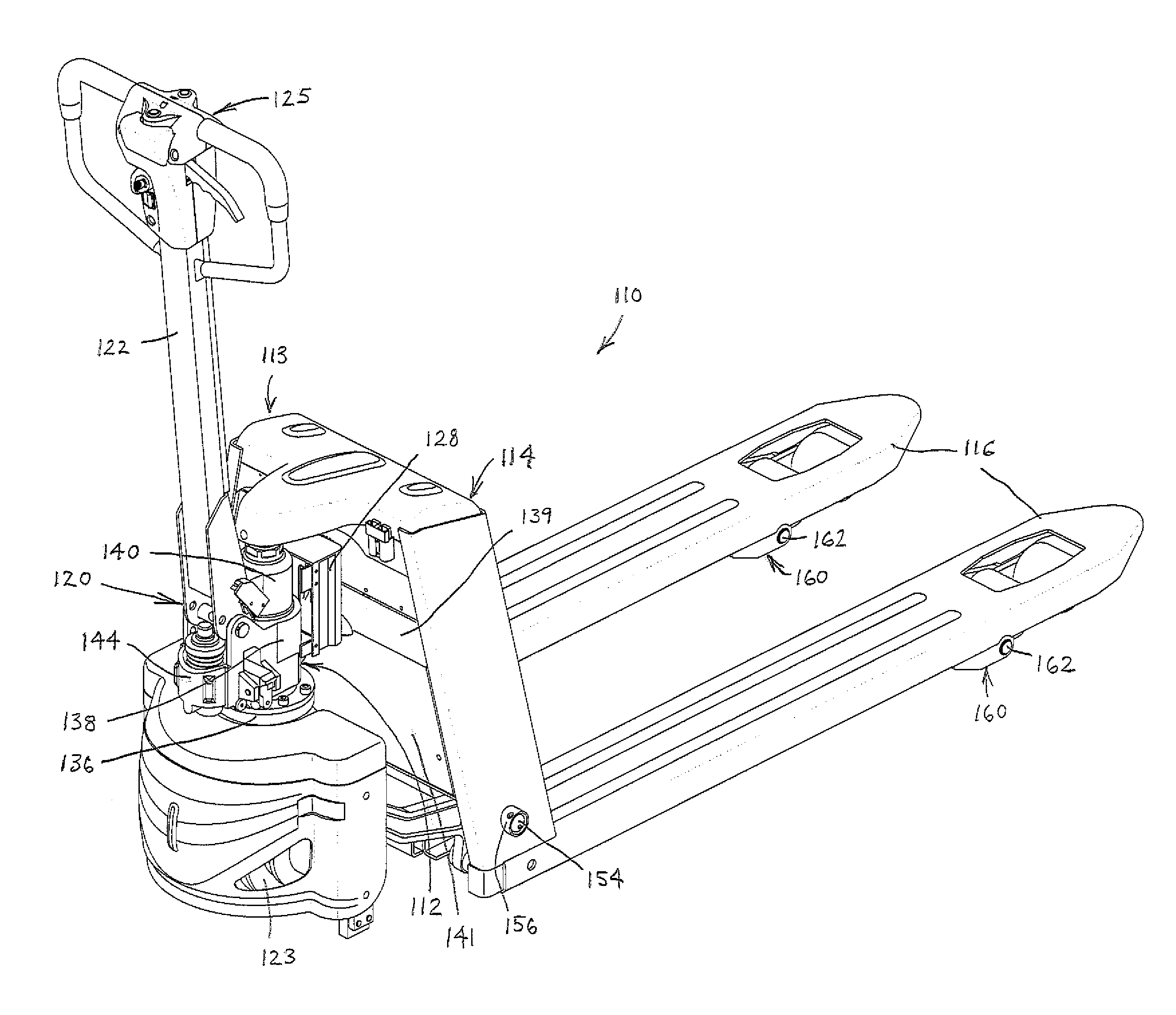
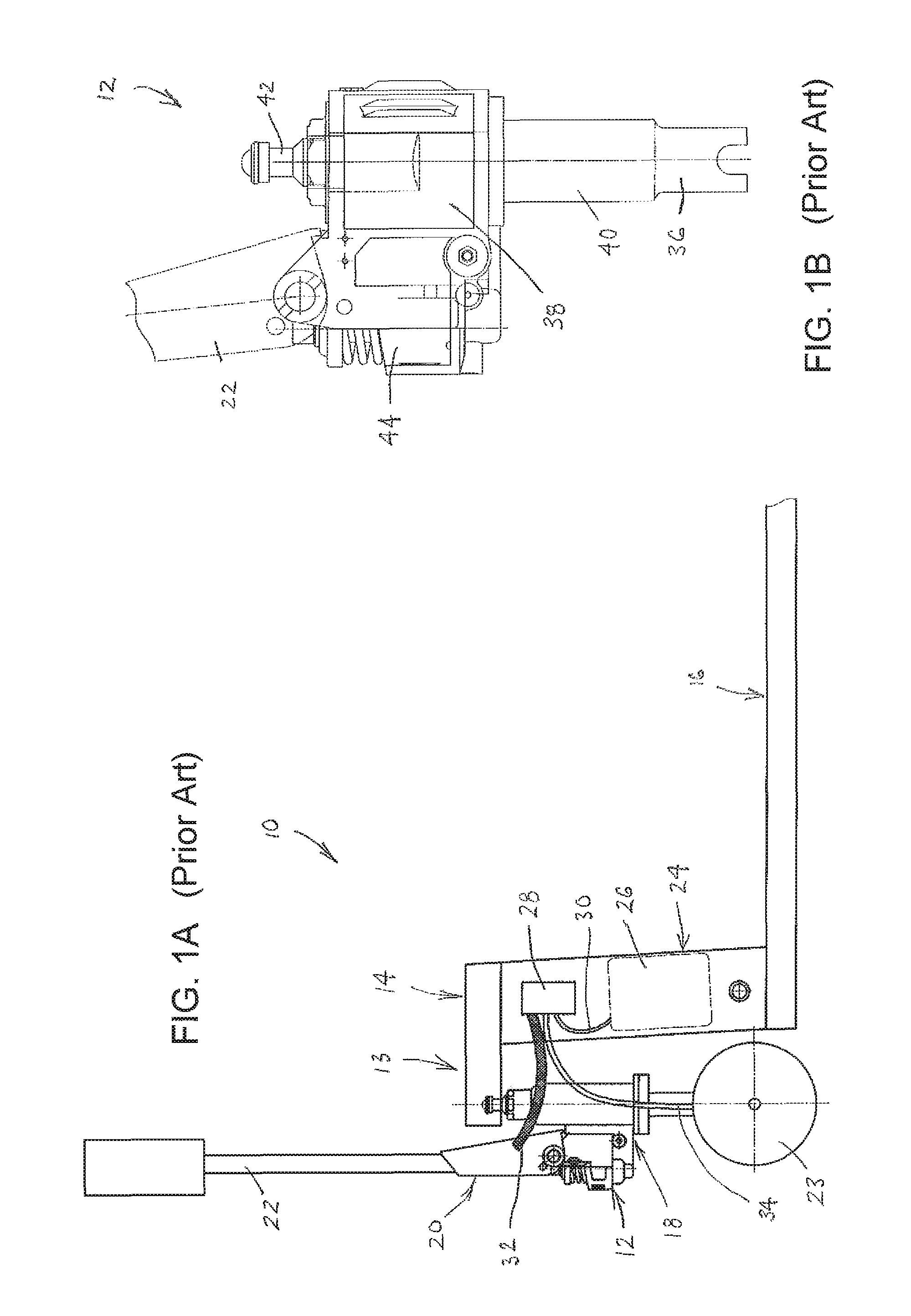
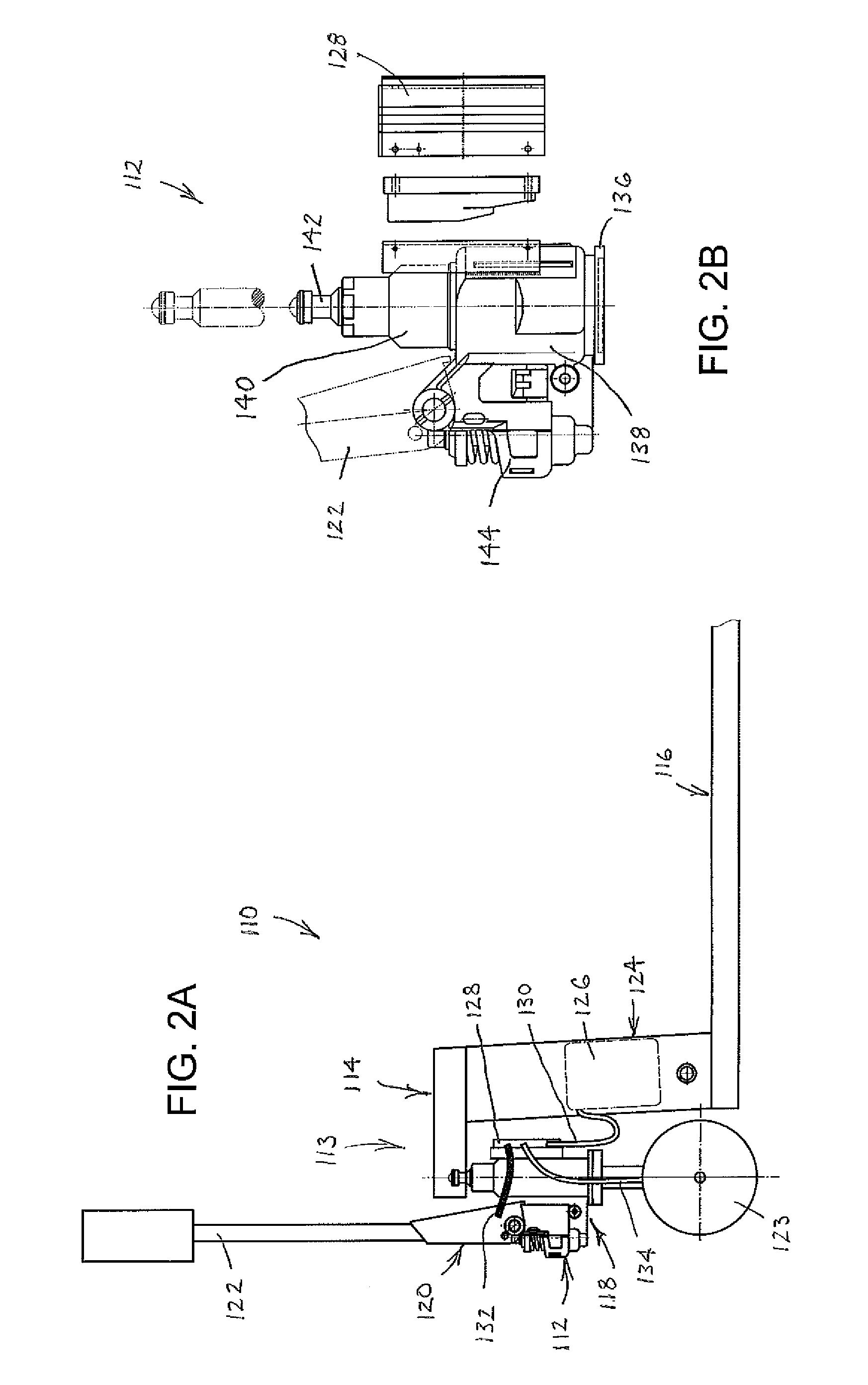
[0023]FIG. 1A shows a simplified diagram of a traditional layout of a pallet truck 10. FIG. 1B shows a hydraulic power unit 12 of the pallet truck 10. The pallet truck 10 generally includes a truck frame 13 having a load lift portion 14 with forks 16 extending forward therefrom. The truck frame 13 further includes a base support portion 18 that is coupled to and rearward of the load lift portion 14. The load lift portion 14 is movable up and down relative to the base support portion 18 to lift and lower pallets and / or goods positioned on the forks 16 relative to the ground.

[0024]A steering mechanism 20 includes an operating handle 22 and a drive wheel 23, wherein the operating handle 22 may be used as a tiller arm to rotate the steering mechanism 20 to direct the rear drive wheel 23 toward the left or right relative to the truck frame 13, so as to steer the pallet truck 10. A power source 24, such as in the form of a battery 26, and a controller 28 are mounted to the load lift porti...


PUM


Abstract

A pallet truck is provided having an electrical system that reduces wear and the likelihood of fracture of the control wiring and output cable by having a controller to which they are connected also be mounted to the steering mechanism that rotates relative to a base support portion of a truck frame, and a hydraulic power unit that permits a reduced size and height, with a manual hydraulic cylinder and cylinder body at a substantially similar height, and the cylinder body and oil storage cavity in a concentric arrangement.

Description

CROSS-REFERENCE TO RELATED APPLICATIONS[0001]This application claims priority to Chinese Patent Application Nos. 201420418854.7, filed Jul. 25, 2014, and 201420418876.3, filed Jul. 25, 2014, which are hereby incorporated by reference in its entirety.FIELD OF THE INVENTION[0002]This disclosure relates to industrial lift trucks and, in particular, to electrical systems and hydraulic power units of pallet trucks that are used for lifting and transporting objects, such as pallets upon which goods may be placed.BACKGROUND OF THE INVENTION[0003]Pallet trucks often are used to lift and maneuver pallets and goods supported thereon during warehousing and for shipping or transportation. Pallet trucks have been developed to provide varying amounts of functionality to an operator and may be generally categorized as either manual or powered. Manual pallet trucks typically include a truck frame having a load lift portion that includes a frame with forks connected thereto, a base support portion o...

Claims


Application Information

Patent Timeline
Patent Type & Authority Patents(United States)
IPC IPC(8): B66F3/24B62B3/00B62B3/06B62B5/00
CPCB62B3/001B62B3/0612B62B3/0618B62B5/0053B62B5/0069
Inventor LIU, YUANWEIMENG, FEIQUANHE, JINHUI
Owner BIG ELEVATOR
Why Eureka
Try Eureka