Supercharge Your Innovation With Domain-Expert AI Agents!

Lighting device with fan directed airflow and air filtering

a technology of fan-directed airflow and light-emitting device, which is applied in the direction of lighting and heating apparatus, dispersed particle separation, separation process, etc., can solve problems such as damage to electrical components

Inactive Publication Date: 2016-10-25
LG ELECTRONICS INC
View PDF19 Cites 0 Cited by
  • Summary
  • Abstract
  • Description
  • Claims
  • Application Information

AI Technical Summary

Benefits of technology

This patent is about a lighting device that prevents outside dust and bugs from getting inside while cooling off an internal component using external air. The technical effect of this device is that it helps to keep the lighting device clean and free from damage caused by external factors.

Problems solved by technology

Electric components located within a casing of a lighting device generate much heat, and in order to cool the electric components, the electric components should be cooled using external air and there is a problem that the electric components are damaged by dust and insects introduced from the outside when introducing external air.

Method used


Image

  • Lighting device with fan directed airflow and air filtering
  • Lighting device with fan directed airflow and air filtering
  • Lighting device with fan directed airflow and air filtering

Examples


Embodiment Construction

[0019]An angle and direction described in a process of describing a structure of a lighting device according to an exemplary embodiment of the present invention are determined based on an angle and direction described in the drawings. In a description on a structure of a lighting device according to an exemplary embodiment of the present invention, when a reference point and a location relationship of an angle are not clearly described, the reference point and a location relationship are used with reference to a related drawing.

[0020]Hereinafter, an exemplary embodiment of the present invention will be described in detail with reference to the drawings.

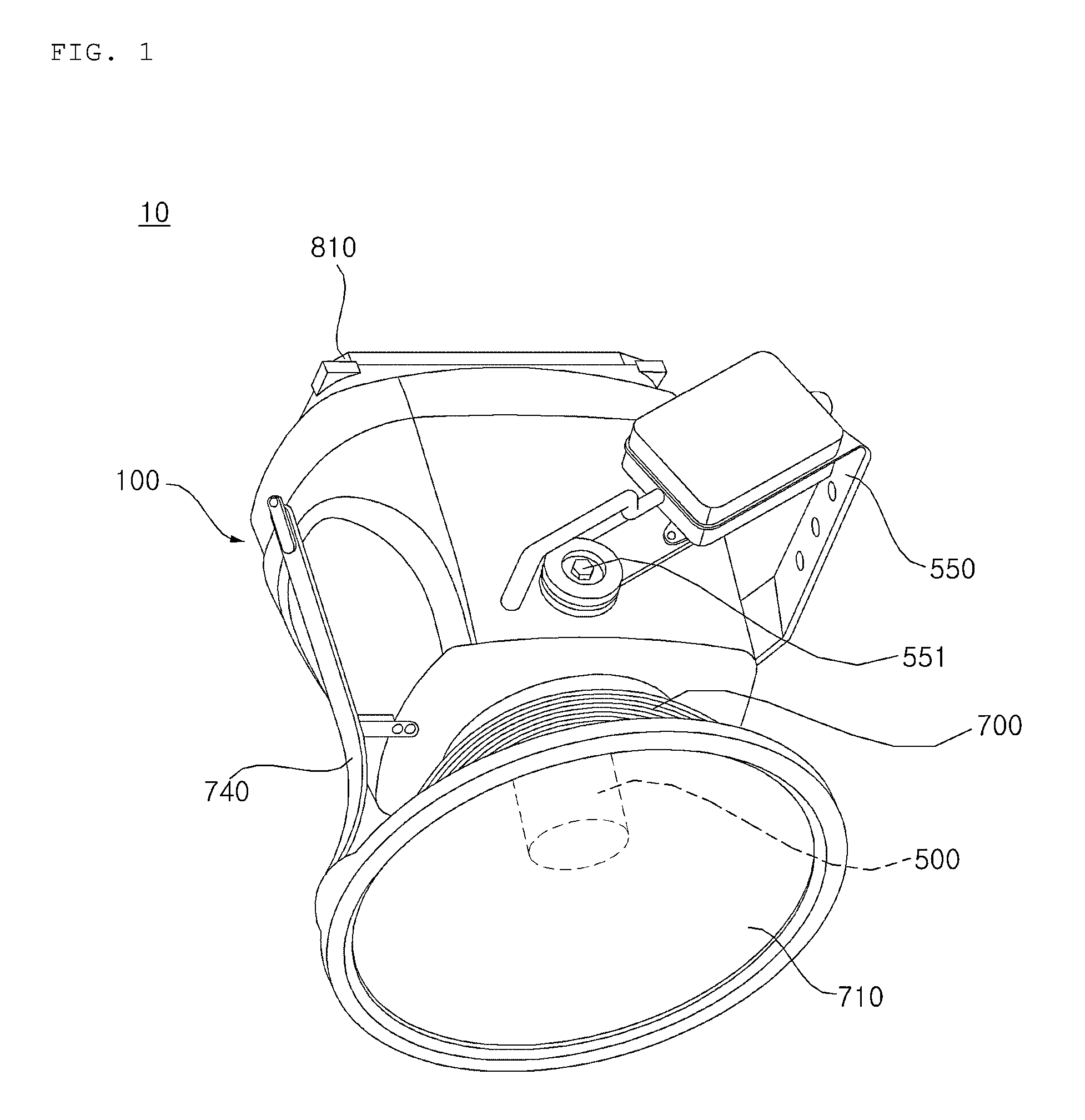
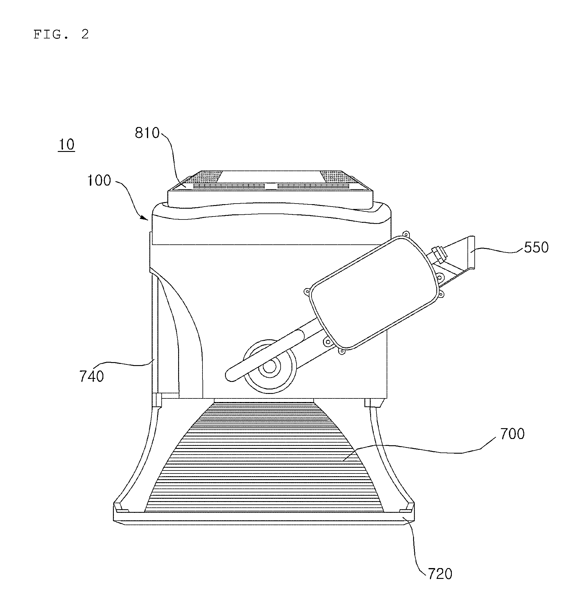
[0021]FIG. 1 is a perspective view of a lighting device according to an exemplary embodiment of the present invention, and FIG. 2 is a side view of the lighting device of FIG. 1.

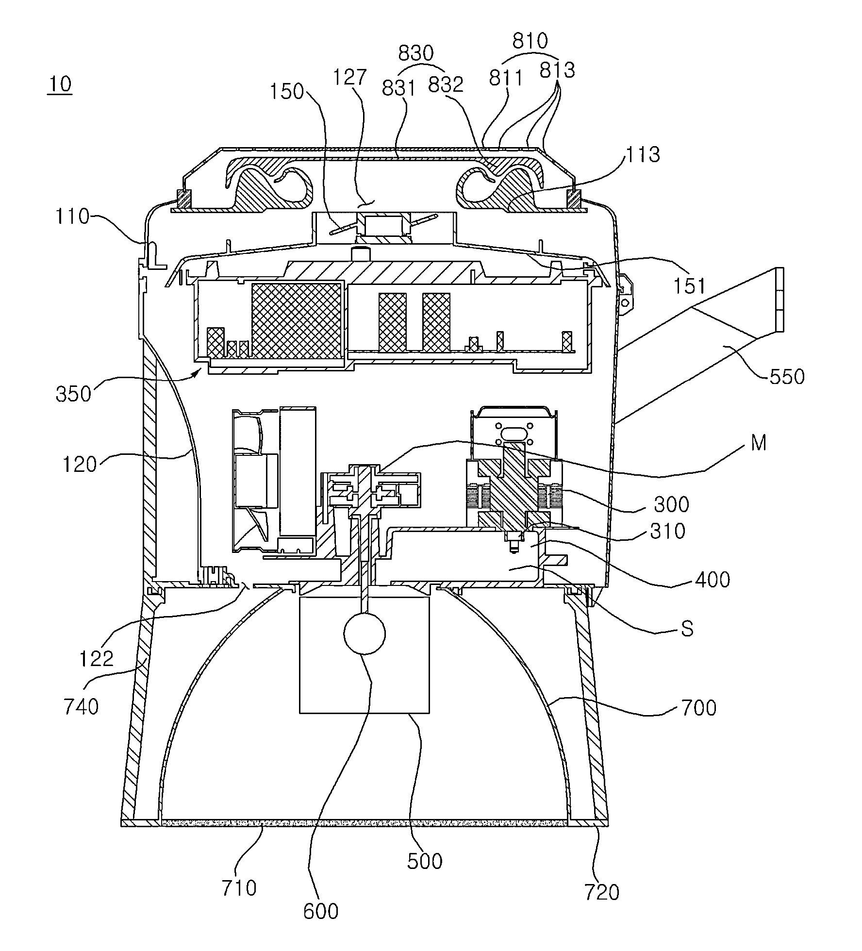
[0022]Referring to FIGS. 1 and 2, a lighting device 10 has a main body forming an external appearance by a casing 100 having a space therein.

[0023]In the casi...


PUM

PropertyMeasurementUnit
internal angleaaaaaaaaaa
areaaaaaaaaaaa
centrifugal forceaaaaaaaaaa

Abstract

A lighting device includes a casing having an inlet that introduces external air at one side and an outlet that discharges the introduced air at the other side. A fan is located within the casing to flow external air from an inlet direction to an outlet direction. An inlet cover blocks at least an upper area of the inlet to prevent external air from being directly introduced into the inlet. An air flow channel communicates the inlet and the outside, and includes two contracting flow channels having a reducing sectional area in an advancing direction of air. The two expanding flow channels communicate with the contracting flow channels and have an increasing sectional area in an advancing direction of air, so that in a connection portion of the contracting flow channel and the expanding flow channel, the advancing direction of air is changed.

Description

CROSS-REFERENCE TO RELATED APPLICATION[0001]This application claims the priority benefit of Korean Patent Application No. 10-2014-0056703, filed on May 12, 2014 in the Korean Intellectual Property Office, the disclosure of which is incorporated herein by reference.BACKGROUND OF THE INVENTION[0002]1. Field of the Invention[0003]The present invention relates to a lighting device.[0004]2. Description of the Related Art[0005]In general, an electrodeless lighting device is a device that transfers microwave energy generated in a microwave generator that generates a microwave, such as a magnetron, to a resonator through a waveguide and that excites a charging material of an electrodeless light bulb provided within the resonator and that generates light when a state of a charging gas of the electrodeless light bulb is converted to a plasma state in this process.[0006]The lighting device is an electrodeless light bulb in which no electrode or filament exists within a light bulb. The electrod...

Claims


Application Information

Patent Timeline
Patent Type & Authority Patents(United States)
IPC IPC(8): H01J61/52F21V29/508F21V29/503H01J65/04F21V29/67B01D45/12B01D45/06F21V29/507F21V29/505
CPCH01J61/523B01D45/06F21V29/503F21V29/508F21V29/67H01J61/52H01J65/044B01D45/12F21V29/505F21V29/507
Inventor HA, JEONGSEOKJUN, YOUNGMINPARK, JUNGSU
Owner LG ELECTRONICS INC
Features
  • R&D
  • Intellectual Property
  • Life Sciences
  • Materials
  • Tech Scout
  • Unparalleled Data Quality
  • Higher Quality Content
  • 60% Fewer Hallucinations
Learn More