Power source module for LED lamp

a technology of power source module and led lamp, which is applied in the direction of semiconductor lamp usage, light and heating apparatus, semiconductor devices for light sources, etc., can solve the problems of led lamp burning, led lamp disadvantages, and high power consumption and heat generation

Active Publication Date: 2016-10-25
JIAXING SUPER LIGHTING ELECTRIC APPLIANCE
View PDF11 Cites 39 Cited by
  • Summary
  • Abstract
  • Description
  • Claims
  • Application Information

AI Technical Summary

Benefits of technology

[0010]The power source module prevents the LED lamp from burning away by a high voltage, so as to enable the LED lamp installed on the traditional fluorescent lamp base to operate normally without modifying the circuit in the base.
[0013]Another object of the present invention is to provide a power source module for a LED lamp having a discharge circuit to prevent the LED lamp from flicker when turning off the LED lamp.

Problems solved by technology

The traditional fluorescent lamp also has the disadvantages of high power consumption and high heat generation.
The starter and the electrical ballast generate a gaseous electric discharge in the fluorescent lamp by raising the voltage, and so it would cause the LED lamp to burn away.
The modification to the electric ballast type fluorescent lamp base is complicated to the user, even to the professional.
Also, it needs manpower and material resources to make the modification.
The inconvenience of the modification to the electric ballast keeps the users from replacing the traditional fluorescent lamp with the LED lamp.

Method used


Image

  • Power source module for LED lamp
  • Power source module for LED lamp
  • Power source module for LED lamp

Examples


Embodiment Construction

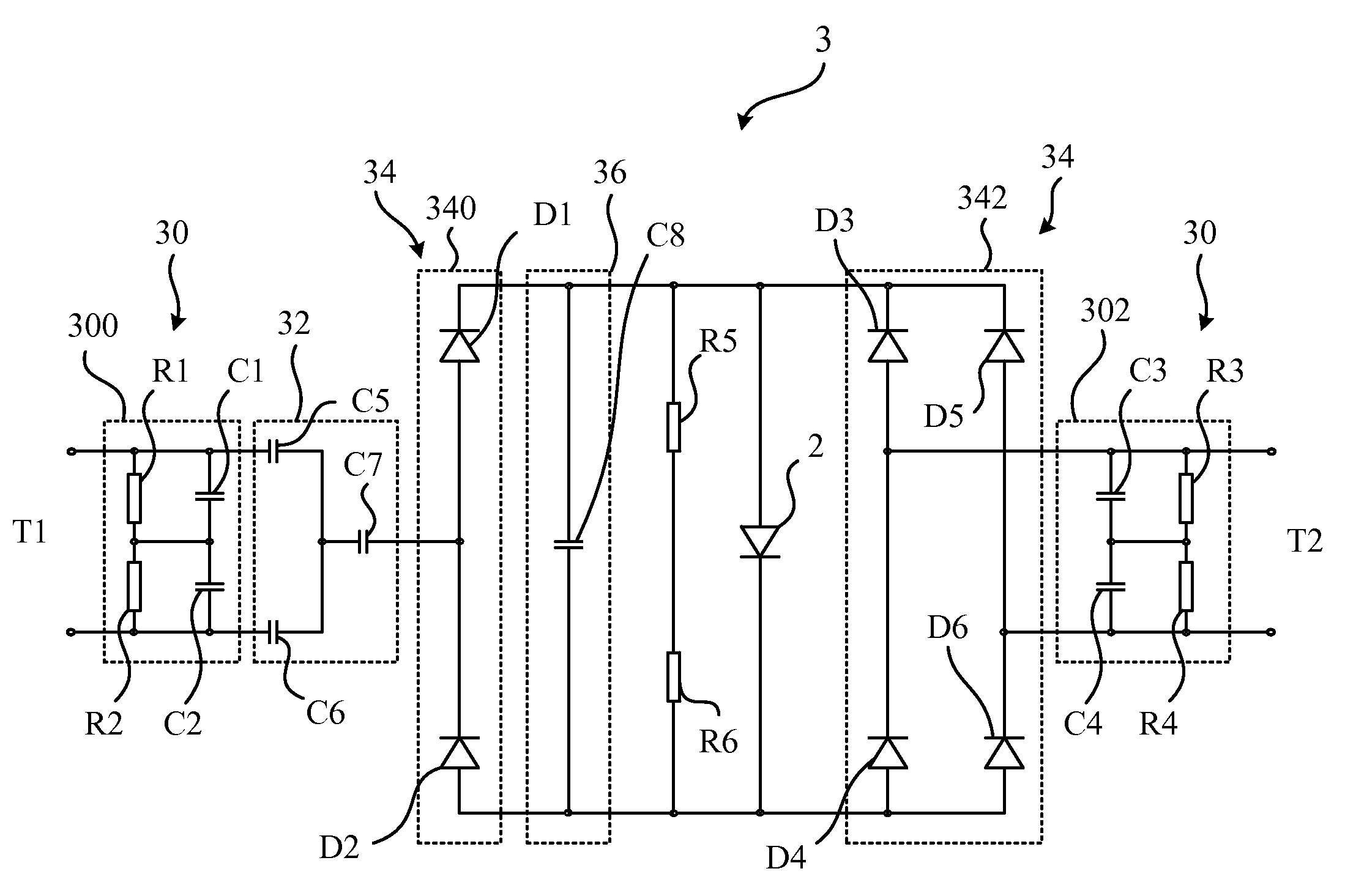
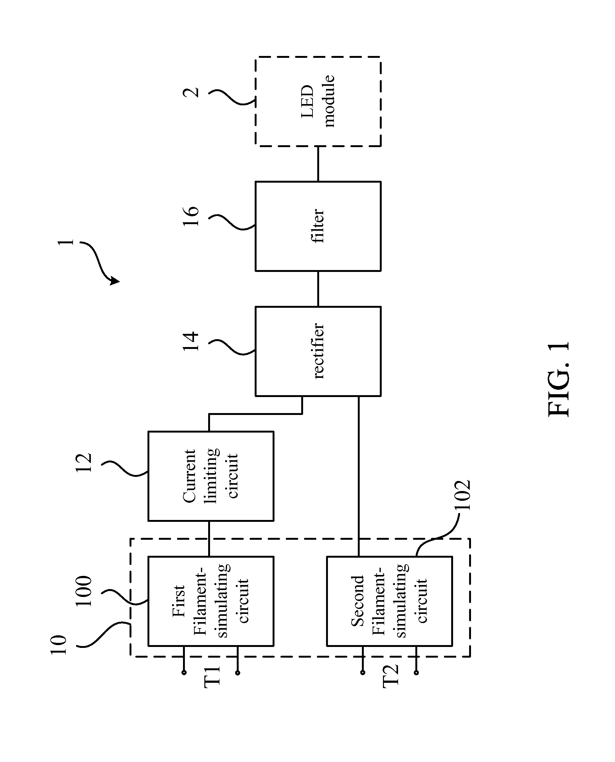
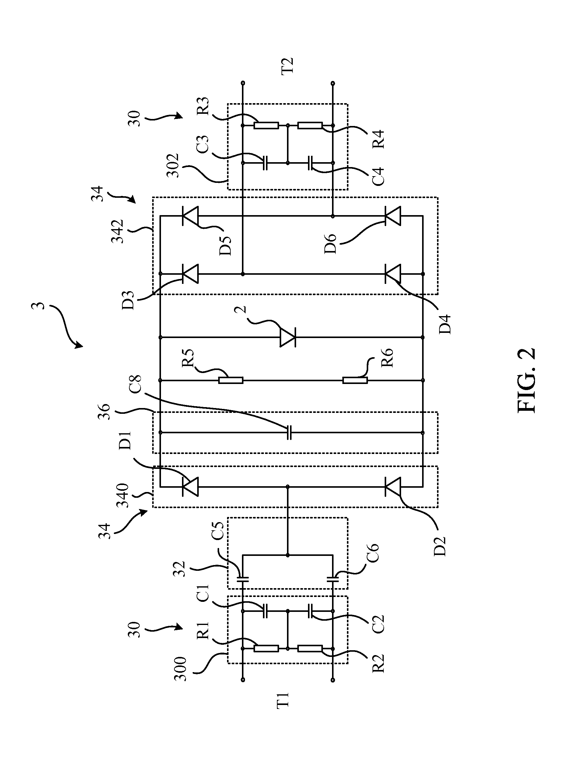
[0019]Please refer to FIG. 1. FIG. 1 is a function block diagram illustrating a power source module 1 for a LED lamp according to an embodiment of the invention. The power source module 1 may be configured inside a casing of the LED lamp to connect a LED module 2 of the LED lamp to terminals of the LED lamp. The LED module includes at least one LED.

[0020]As shown in FIG. 1, the power source module 1 includes a filament-simulating unit 10, a current limiting circuit 12, a rectifier 14, and a filter 16. The filament-simulating unit 10 is electrically connected to the terminals of the LED lamp. The terminals of the LED lamp includes a first bi-pin terminal T1 and a second bi-pin terminal T2, and each of the first and the second bin-pin terminals T1, T2 further include two pins. These pins of the first and the second bin-pin terminals T1, T2 are configured to be detachably installed on the traditional fluorescent lamp base for receiving a current therefrom. The filament-simulating unit ...


PUM


Abstract

A power source module for a LED lamp includes a filament-simulating circuit, a current limiting circuit, a rectifier, a filter, and a discharging circuit electrically connected to each other and a LED in the LED lamp. The filament-simulating circuit simulates a filament before the LED to pass through the pre-heating process of the electrical ballast in a fluorescent lamp base. The current limiting circuit, the rectifier, and the filter limit, rectify and filter the current from an external power source in the fluorescent lamp base to output a high frequency, direct current to drive the LED. The discharging circuit discharges the energy after turning the power switch off to prevent the LED lamp from flicker. Therefore, the power source module enables the LED lamp to be installed on the traditional fluorescent lamp base without modifying the circuit in the base.

Description

PRIORITY CLAIM[0001]This application claims the benefit of the filing date of Chinese Patent Application No. 201420602526.2, filed Oct. 17, 2014, entitled “POWER SOURCE MODULE FOR LED LAMP,” and the contents of which are hereby incorporated by reference in their entirety.FIELD OF THE INVENTION[0002]The invention relates to a power source module for a LED lamp, and more particularly, the invention relates to a power source module for enabling the LED lamp installed on the traditional fluorescent lamp base.BACKGROUND[0003]The fluorescent lamps have been used wildly in the world for illumination. The traditional fluorescent lamp is detachably installed on a fluorescent lamp base to receive the power from the power source in the base to emit light. According to the principle of luminosity of the traditional fluorescent lamp, the fluorescent lamp base has to provide a starter and a ballast to drive the traditional fluorescent lamp. The starter is used for heating filaments in the fluores...

Claims


Application Information

Patent Timeline
Patent Type & Authority Patents(United States)
IPC IPC(8): H05B33/08F21V23/00F21V23/02F21K99/00H05B44/00
CPCH05B33/0812F21K9/27F21V23/009F21V23/023H05B33/0809H05B45/395Y02B20/30F21K9/278
Inventor YE, QI FENGJIANG, TAOZHANG, YUE-QIANGCHEN, ZHONG
Owner JIAXING SUPER LIGHTING ELECTRIC APPLIANCE
Why Eureka
Try Eureka