Oven having an H-shaped rotating door

a technology of rotating doors and ovens, which is applied in the direction of domestic stoves or ranges, heating types, lighting and heating apparatus, etc., can solve the problems of enormous heat loss, conveyor ovens also have disadvantages, and limit the number of substantially identical food items placed in the oven

Active Publication Date: 2016-11-01
OVENTION
View PDF51 Cites 79 Cited by
  • Summary
  • Abstract
  • Description
  • Claims
  • Application Information

AI Technical Summary

Benefits of technology

[0013]More particularly, the present invention relates to an oven comprising a housing, a cavity located within the housing, wherein the housing includes an opening into the cavity, an H-shaped rotating door comprising a first food loading section and a second food loading section, a motor for rotating the H-shaped rotating door, and a heat source for providing heat to the cavity to heat up any food item placed on one of the first and second food loading sections located within the cavity. The H-shaped rotating door serves as a cover to prevent heat within the cavity from escaping through the opening when one of the first and second loading sections is placed within the cavity.

Problems solved by technology

The only limit to how many substantially identical food items may be placed in the conveyor oven is the speed of the conveyor belt, which correlates to the residence time inside the heated cavity for food items to be sufficiently cooked.
However, conveyor ovens also have their disadvantages.
Conveyor ovens are very efficient when cooking similar food items, but not for cooking a variety of food items that require vastly different cooking times and heat transfer profiles.
In addition, the two openings contribute to tremendous heat loss during the operation of conveyor ovens.
The lost heat must be replaced in order to maintain cook temperature, and as a result conveyer ovens are not energy efficient.
Furthermore, the space required by the loading and unloading platforms of conveyor ovens limit the application of conveyor ovens to relatively large commercial kitchens.

Method used


Image

  • Oven having an H-shaped rotating door
  • Oven having an H-shaped rotating door
  • Oven having an H-shaped rotating door

Examples


Embodiment Construction

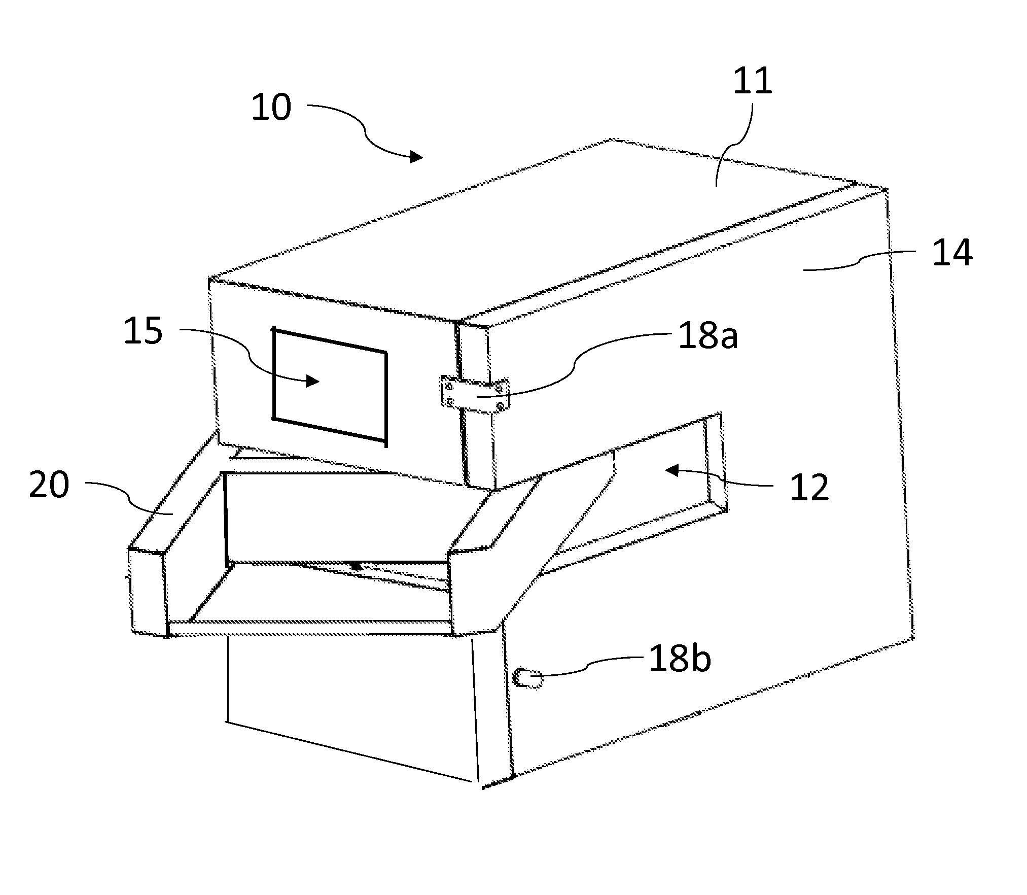
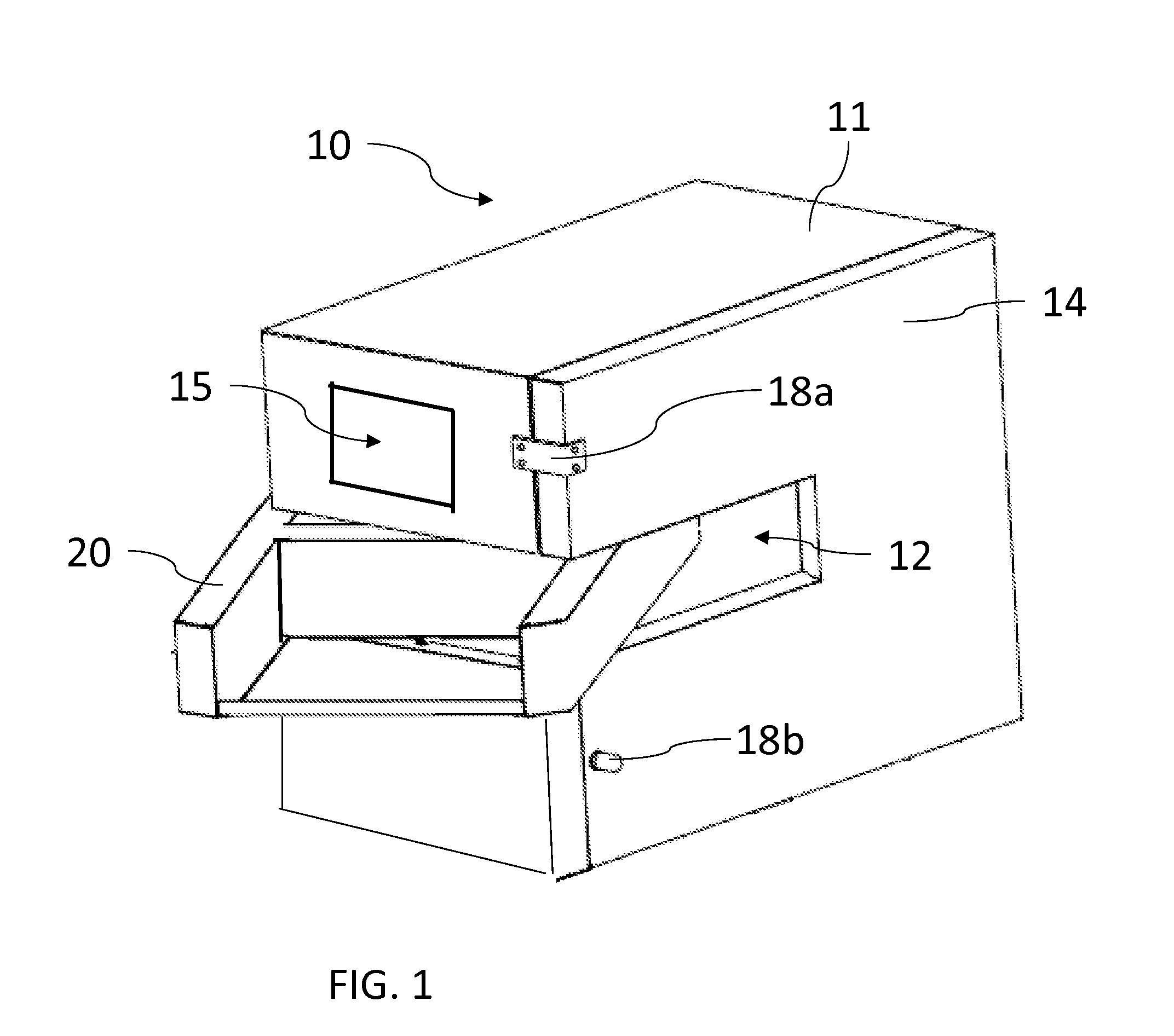
[0017]Referring now to the drawings and in particular to FIG. 1, there is depicted an isometric view of an oven, in accordance with an exemplary embodiment of the present invention. As shown, an oven 10 includes a housing 11 having an opening 12, a side access panel 14 and an H-shaped rotating door 20. As the name implies, H-shaped door 20 is a rotatable oven door formed in the shape of a letter “H” or the like. The size and dimension of opening 12 and H-shaped rotating door 20 may be designed to accommodate the largest food item that can be allowed to be placed within the oven 10. Side access panel 14 may be secured to housing 11 via latches 18a and 18b. Side access panel 14 may serve as a door to access the inside of the oven 10 for the purposes of, for example, cleaning, maintenance, and / or repair.

[0018]The oven 10 may also include a control panel 15. Control panel 15 may be implemented with a touchscreen, a keypad, a liquid crystal display (LCD), and / or other means for entering ...


PUM


Abstract

An oven comprising a housing, a cavity, an H-shaped rotating door, a motor and a heat source is disclosed. The cavity, which includes an opening, is located within the housing. The H-shaped rotating door, which can be rotated by the motor, includes a first food loading section and a second food loading section. The H-shaped rotating door also serves as a cover to prevent heat within the cavity from escaping through the opening. The heat source provides heat to the cavity to heat up any food item placed on one of the food loading sections located within the cavity.

Description

CROSS REFERENCE TO RELATED APPLICATIONS[0001]This application is a continuation-in-part of U.S. application Ser. No. 14 / 045,257, filed on Oct. 3, 2013, which is a continuation-in-part of U.S. application Ser. No. 13 / 077,143, filed on Mar. 31, 2011, a continuation-in-part of U.S. application Ser. No. 13 / 236,695, filed on Sep. 20, 2011, now U.S. Pat. No. 8,733,236, and a continuation-in-part of U.S. application Ser. No. 13 / 774,617, filed on Feb. 22, 2013, now U.S. Pat. No. 8,746,134, the entire contents of each of which are incorporated herein by reference.FIELD OF INVENTION[0002]The present invention relates to compact ovens in general, and in particular to an oven having an H-shaped rotating door, which is capable of providing continuous food cooking while minimizing heat loss.BACKGROUND OF THE INVENTION[0003]A conveyor oven typically has a first opening through which uncooked food enters and a second opening at the opposite end of the oven through which cooked food exits. A stainle...

Claims


Application Information

Patent Timeline
Patent Type & Authority Patents(United States)
IPC IPC(8): A47J37/04F24C15/16F24C15/32A21B3/07A21B1/44A21B1/42A21B1/26H05B6/64A47J37/06A21B1/24
CPCA47J37/049A21B1/245A21B1/26A21B1/42A21B1/44A21B3/07A47J37/043A47J37/067A47J37/0641F24C15/162F24C15/322F24C15/325H05B6/6411H05B6/6414H05B6/6473A47J37/041A47J37/0629H05B1/0263
Inventor MCKEE, PHILIP R.DENMAN, JOHN
Owner OVENTION
Why Eureka
Try Eureka