
Aeroacoustic duster

a duster and air technology, applied in the direction of suction nozzles, etc., can solve the problems of considerable surface wear and conventional vacuum cleaners, and achieve the effect of efficiently impinging fluid, and efficiently removing dust particles

Active Publication Date: 2016-11-01
UNIVERSITY OF VERMONT
View PDF1 Cites 38 Cited by
  • Summary
  • Abstract
  • Description
  • Claims
  • Application Information

AI Technical Summary

Benefits of technology

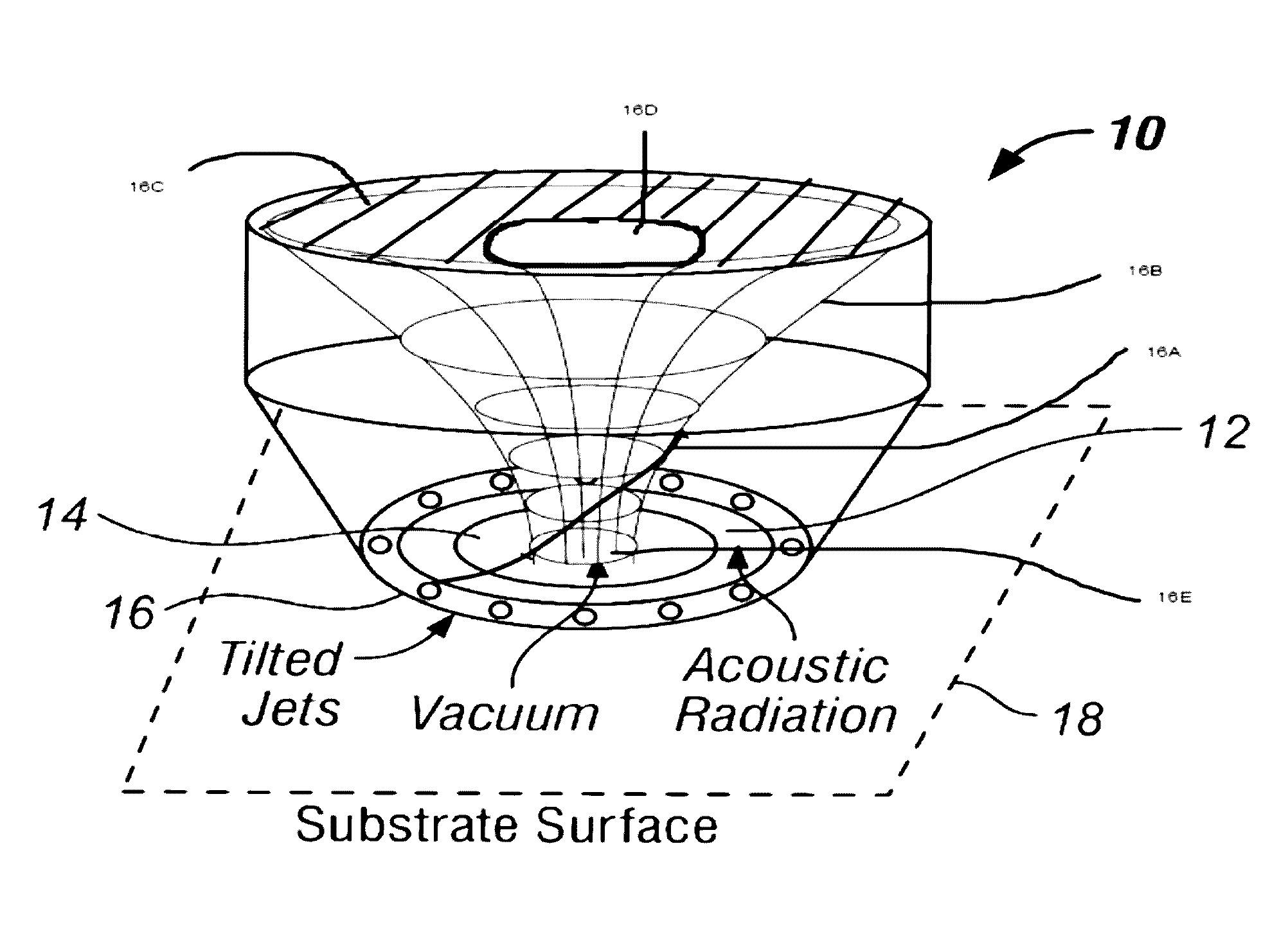
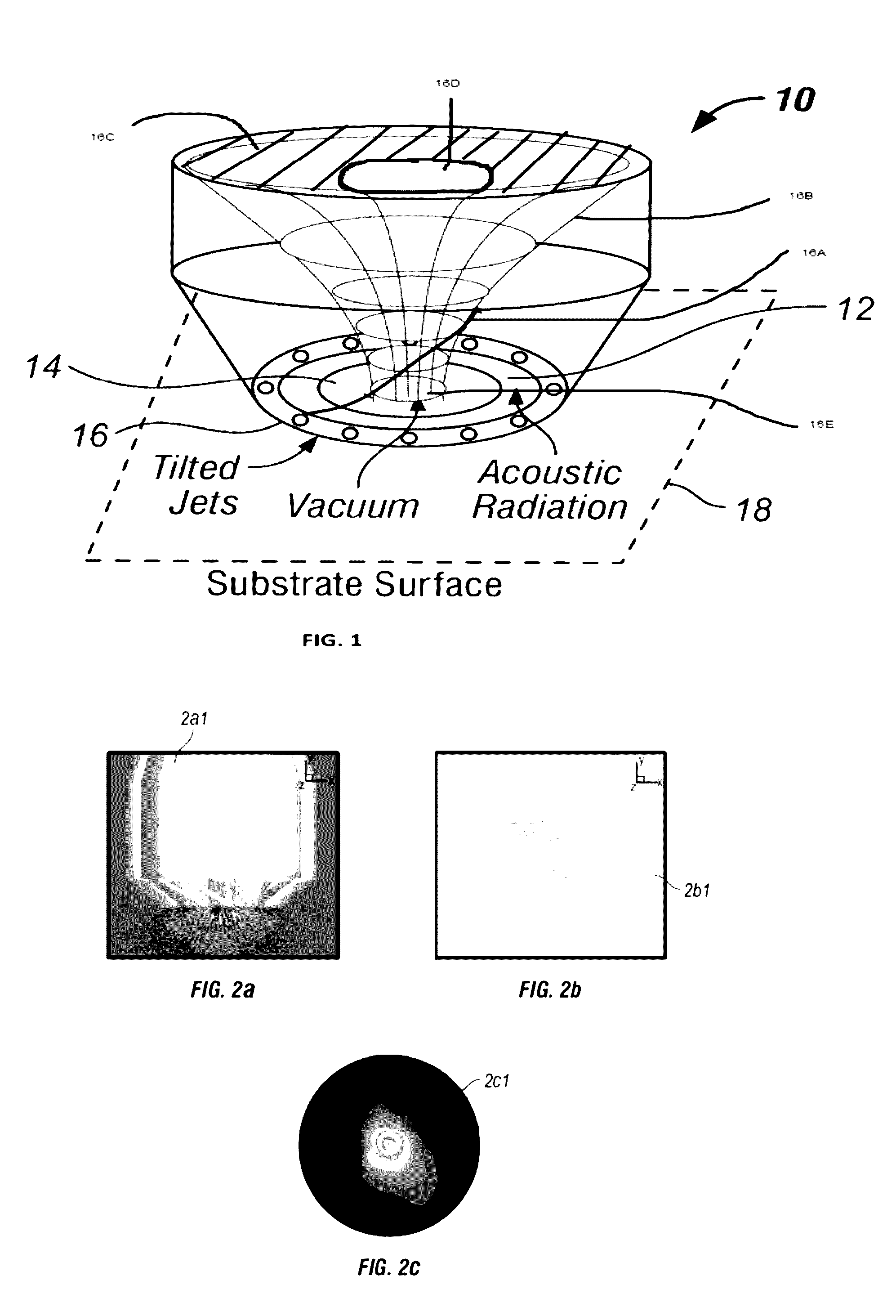
[0009]The foregoing and other problems are overcome, and other advantages are realized, in accordance with the presently preferred embodiments of these teachings. The aero-acoustic duster device is intended to provide for high particle removal rate from surfaces with low energy expenditure relative to competing vacuum-based devices. The device removes particulate matter from a surface using a wall normal standing vortex. The wall normal standing vortex is generated over the surface, with suction in the vortex center and jets for blowing air along the periphery. The jets are tilted in the tangential direction to induce vortex motion within the suction region. The vortex is said to be bonded, or wall normal, because streamlines originating in the jets are entrained back into the central vortex. The wall normal vortex acts to enhance shear stress under the suction region, hence increasing the ability of the air flow to entrain particles.
[0011]In accordance with one embodiment of the present invention an apparatus for efficiently removing dust particles is provided. The apparatus includes bounded vortex generator for generating, a wall normal standing vortex. The bounded vortex generator includes a plurality of tilted jets for providing tangential air flow across a dusted substrate, and a vacuum port for vacuuming dust excited by the tangential air flow combination.
[0013]The invention is also directed towards an apparatus for efficiently removing dust particles from a surface without direct contact. The apparatus includes a plurality of tilted annular jets arranged around a common axis for providing an air flow substantially tangential to the surface and a circular vacuum port for providing dust removing, suction. The circular vacuum port suction and the plurality of tilted annular jets are adaptable to operate conjunctively to form a standing vortex with a high shear stress region tangential to the surface to efficiently remove the dust particles. The apparatus also includes an impingement surface parallel to the surface to be cleaned, wherein the impingement surface is separated from the surface to be cleaned by a predetermined distance.
[0014]The invention is also directed towards an apparatus for efficiently impinging fluid onto a surface to remove particles and / or heat from the surface, the apparatus includes a plurality of tilted annular jets arranged around a common axis for providing a radial and tangential air flow component, wherein each tilted annular jet comprises a tilt angle with respect to a standing vortex and wherein each tilt angle is proportional with the flow rate ratio. The apparatus also includes a circular vacuum port for providing negative air pressure. The circular vacuum port suction and the plurality of tilted annular jets are adaptable to operate conjunctively to form a standing vortex with a high shear stress region tangential to the surface to efficiently remove the dust particles and / or maximize heat transfer away from the surface.

Problems solved by technology

Hence, conventional vacuum cleaners cause considerable surface wear.

Method used


Image

  • Aeroacoustic duster
  • Aeroacoustic duster
  • Aeroacoustic duster

Examples


Embodiment Construction

[0035]The following brief definition of terms shall apply throughout the application:

[0036]The term “comprising” means including but not limited, to, and should be interpreted in the manner it is typically used in the patent context;

[0037]The phrases “in one embodiment,”“according to one embodiment,” and the like generally mean that the particular feature, structure, or characteristic following, the phrase may be included in at least one embodiment of the present invention, and may be included in more than one embodiment of the present invention (importantly, such phrases do not necessarily refer to the same embodiment);

[0038]If the specification describes something as “exemplary” or an “example,” it should be understood that refers to a non-exclusive example; and

[0039]If the specification states a component or feature “may”“can,”“could,”“should,”“preferably,”“possibly,”“typically,”“optionally,”“for example,” or “might” (or other such language) be included or have a characteristic, ...


PUM


Abstract

The invention disclosed herein provides for high particle removal rate and / or heat transfer from surfaces. The device removes particulate matter from a surface using a bounded vortex generated over the surface, with suction in the vortex center and jets for blowing air along the periphery. The jets are tilted in the tangential direction to induce vortex motion within the suction region. The vortex is said to be bounded because streamlines originating in the downward jets are entrained back into the central vortex.

Description

REFERENCE TO U.S. GOVERNMENT INTEREST[0001]“The U.S. Government has a paid-up license in this invention and the right, in limited circumstances to require the patent owner to license others on reasonable terms as provided for by the terms of Grant NNX08AZ07A awarded by NASA.”CROSS-REFERENCE TO RELATED APPLICATIONS[0002]The present application is related to, claims the earliest available effective filing date(s) from, and incorporates by reference in its entirety all subject matter of the following listed application(s) (the “Related Applications”) to the extent such subject matter is not inconsistent herewith; and the present application also claims the earliest available effective filing date(s) from, and also incorporates by reference in its entirety all subject matter of any and all parent, grandparent, great-grandparent, etc. applications of the Related Application(s) to the extent such subject matter is not inconsistent herewith:[0003]1. U.S. patent application Ser. No. 13 / 024,...

Claims


Application Information

Patent Timeline
Patent Type & Authority Patents(United States)
IPC IPC(8): A47L9/02A47L9/08
CPCA47L9/02A47L9/08
Inventor MARSHALL, JEFFREY S.HITT, DARRENWU, JUN-RUVACHON, NICHOLAS M.CHEN, DI
Owner UNIVERSITY OF VERMONT
Learn More