Dual release lanyard connector

a technology of lanyard connector and umbilical cord, which is applied in the direction of belt/chain/gearring, mechanical equipment, textile cables, etc., can solve the problems of connector damage, connector ratcheting, and aircraft airframe damage,

Active Publication Date: 2016-11-01
EATON INTELLIGENT POWER LTD
View PDF16 Cites 3 Cited by
  • Summary
  • Abstract
  • Description
  • Claims
  • Application Information

AI Technical Summary

Problems solved by technology

However, as the connector begins disconnecting from the ordinance receptacle, the primary spring acts to close the threaded segments and “ratcheting” may occur, whereby the threaded segments become caught on threading or the receptacle as the connector is being pulled free.
As a result, the connector may be destroyed, which in turn may damage the umbilical cable, as well as the aircraft airframe.
The cost of replacing damaged connectors and cables, as well as repairing damaged airframes is high.
However, it is recognized that existing dual release connectors utilize a primary spring—similar to the single release connector described above—and often utilize a common release path in the connector for the primary and secondary lanyard cables, which provides less than optimal functionality in the connector for releasing the ordinance.

Method used


Image

  • Dual release lanyard connector
  • Dual release lanyard connector
  • Dual release lanyard connector

Examples


Embodiment Construction

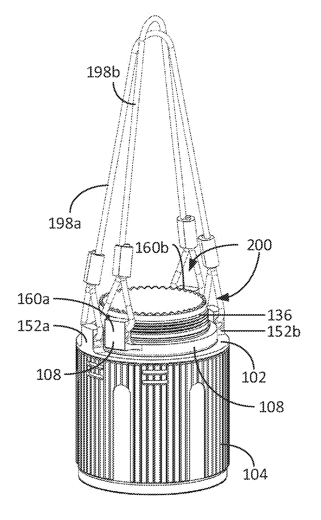
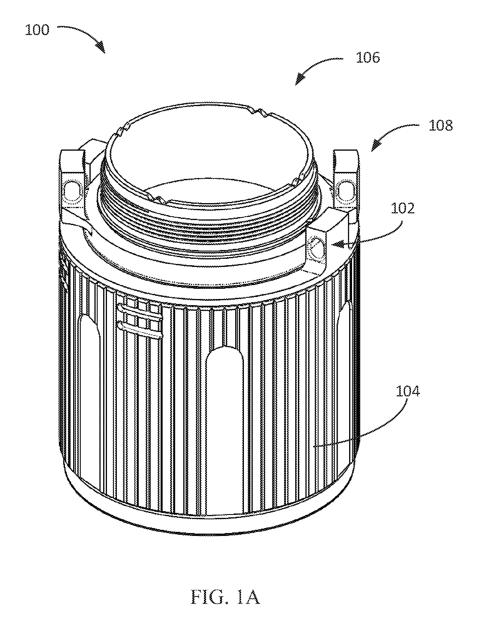
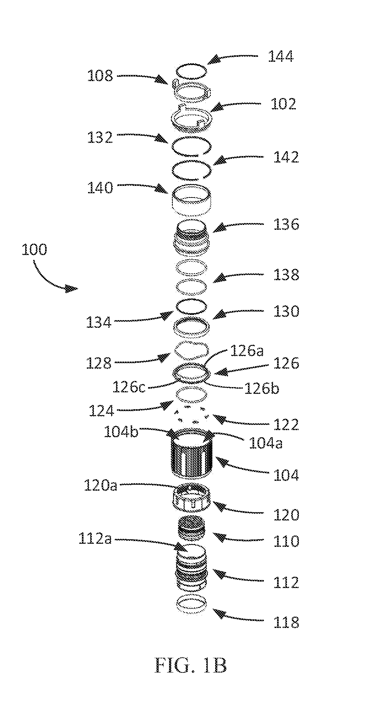
[0032]Embodiments of the present invention are directed to a dual release lanyard connector that provides redundant separation capability via separate primary and secondary release paths. The dual release lanyard connector also provides reset and multiple testing capabilities. The dual release lanyard connector interfaces between a lanyard cable and an ordinance to be released from an aircraft and is generally capable of handling the forces associated with the release of the ordinance. Generally, the dual release lanyard connector has more longevity than existing lanyard connectors in the market.

[0033]The invention may be better understood by reading the following description of non-limitative, exemplary embodiments with reference to the attached drawings wherein like parts of each of the figures are identified by the same reference characters.

[0034]FIGS. 1A-1C illustrate top perspective, exploded, and side cross-sectional views of a dual release lanyard connector 100, according to ...


PUM


Abstract

A dual release lanyard connector includes first and second lanyard rings coupleable to first and second lanyard cables, a coupling sleeve coupled to the first lanyard ring and movable between a first position and a second position, and a locking ring configured to engage the coupling sleeve and movable between the first position and the second position, the locking ring having a first ring groove. A two-piece housing of the lanyard connector includes a plug housing with first and second plug housing grooves and a secondary housing coupled to the second lanyard ring and having a secondary housing groove, the secondary housing movable between a third position and a fourth position. The secondary housing is configured to engage the coupling sleeve such that movement of the secondary housing to the fourth position causes a corresponding movement of the coupling sleeve and locking ring to the second position.

Description

BACKGROUND OF THE INVENTION[0001]The present invention relates generally to lanyard connectors. More particularly, the present invention is directed to a dual release umbilical connector for releasing an ordinance from an aircraft.[0002]An aircraft carrying an ordinance, such as a weapon, typically utilizes an umbilical connector and a single loop contiguous lanyard for release of the ordinance. The connector interfaces between the ordinance and a lanyard cable, and the lanyard cable is looped around an aircraft mounted post, also known as a “bail bar.”[0003]The ordinance mounts to the connector using a receptacle on the ordinance, and the ordinance is held in place by a coupling ring and a number of threaded segments. Conventional lanyard connectors utilize a single primary compression type spring that prevents the coupling ring from shifting and allowing release of the connector. Upon pulling the lanyard cable during aircraft ordinance release, the primary spring compresses. Compr...

Claims


Application Information

Patent Timeline
Patent Type & Authority Patents(United States)
IPC IPC(8): H01R13/73B64D1/04F16G11/10
CPCB64D1/04F16G11/10
Inventor LAUGHLIN, PATRICK JOHN
Owner EATON INTELLIGENT POWER LTD
Why Eureka
Try Eureka