Structured sliding surface of a bearing shell

a bearing shell and sliding surface technology, applied in the direction of sliding contact bearings, manufacturing tools, portable drilling machines, etc., can solve the problems of bearing wear and disadvantageous engine running behaviour, and achieve the effect of improving wear properties

Active Publication Date: 2016-11-01
FEDERAL MOGUL WIESBADEN
View PDF37 Cites 1 Cited by
  • Summary
  • Abstract
  • Description
  • Claims
  • Application Information

AI Technical Summary

Benefits of technology

[0009]The object of the present invention is to provide a bearing shell having improved wear properties, a tool as well as a method for producing such a bearing shell.
[0010]The tool according to the invention comprises a preferably cylindrical drilling spindle, which is driven by a rotary drive and simultaneously implements a feed movement. The drilling spindle rotates about a rotational axis and comprises at least one first cutting cartridge that is mounted on or inserted in the drilling spindle at the outer circumference. During the machining of a bearing shell, a cutting region of the cutting cartridge comes into contact with the sliding layer of the bearing shell and cuts the bearing shell to a certain wall thickness upon rotation of the drilling spindle, as a result of which the actual sliding surface is also simultaneously produced. According to the invention, the first cutting cartridge can be adjusted in its axial direction by an adjusting means during operation of the tool. The direction of adjustment differs from the direction of the rotational axis, and thus the direction of adjustment has a non-zero component in the direction perpendicular to the rotational axis. This allows a profile to be realised in a targeted manner in the sliding region of the bearing shell when drilling out the bearing shell. If, as a result of the process, the bearing shell experiences a very uniform profiling as described above, this profiling is superimposed by the targeted profiling. This targeted structuring is thus to be distinguished from a possibly inevitably realised minimal groove profiling, and is also distinguishable owing to the uniformity of the profiling that occurs as a result of the process. Owing to the targeted profiling, the build-up of lubricating film between the sliding bearing shell and the shaft mounted therein is improved, the emergency running properties during operation are improved, and a reduction in the oil losses at the sliding bearing site during operation is achieved. These advantages are achieved in that minimal bending or tilting of the shaft during operation and under load is compensated or is at least reduced by a sliding surface geometry which is adapted to the operating conditions.
[0012]The drilling spindle preferably comprises at least one second cutting cartridge. For this purpose, the first cutting cartridge is preferably arranged offset behind the second cutting cartridge in the feed direction of the tool. The two cutting cartridges are preferably mounted opposite one another at 180° on the drilling spindle. By means of a suitable positioning of the second cutting cartridge and a tilting of the drilling tool in respect of the bearing shell axis during machining, exposed surfaces can be formed at the ends of the bearing shell. By means of the exposed regions, it is prevented that imprecisions at the connection sites of the two bearing shells lead to the inner edge of a partial surface at a connection site protruding inwardly. As a result hereof, the running properties of the shaft are improved and the wear on the bearing and the shaft is reduced. With just one tool and just one drilling-out step, two measures for optimising wear and improving running properties can be realised in this manner. A separate machining step for realising the targeted profiling is not necessary. A synergetic effect of the two measures lies therein.
[0014]The adjusting means preferably comprises or comprise (in the case of a plurality of adjustable cutting cartridges) a piezo element. The possibility of adjustment is thus created continuously or at a certain frequency by a piezo element which is preferably disposed in the drilling spindle head. The cutting cartridge is structurally arranged in the spindle head such that it is preferably braced against the piezo element. By means of a corresponding actuation of the piezo element, this element expands and thus alters the position of the cutting cartridge in the axial direction. Owing to the short reaction times and the precision with which the piezo element works, a possibility for adjusting the cutting cartridge, which is suitable for the machining process, is hereby created.

Problems solved by technology

This phenomenon occurs as a result of the process and is unavoidable when using a cutting tool of the type described above.
A further cause of wear on the bearing and the shaft mounted therein is a minimal bending or tilting when a load is applied to the shaft.
If the bearing is a connecting rod eye or another bearing that is subject to high loads in internal combustion engines, these uneven loads of the shaft on the bearing ultimately have a disadvantageous effect on the running behaviour of the engine.

Method used


Image

  • Structured sliding surface of a bearing shell
  • Structured sliding surface of a bearing shell

Examples


Embodiment Construction

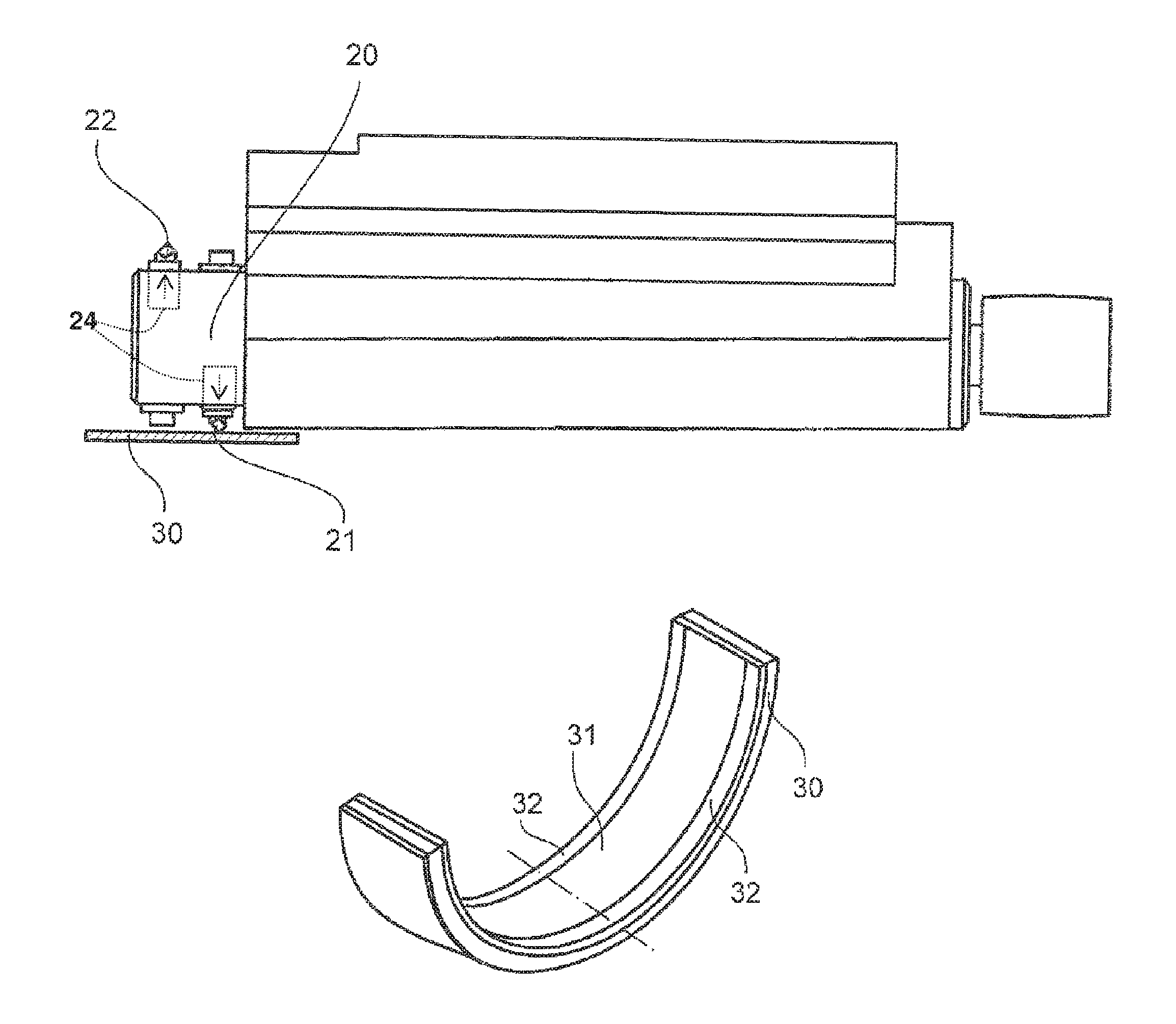
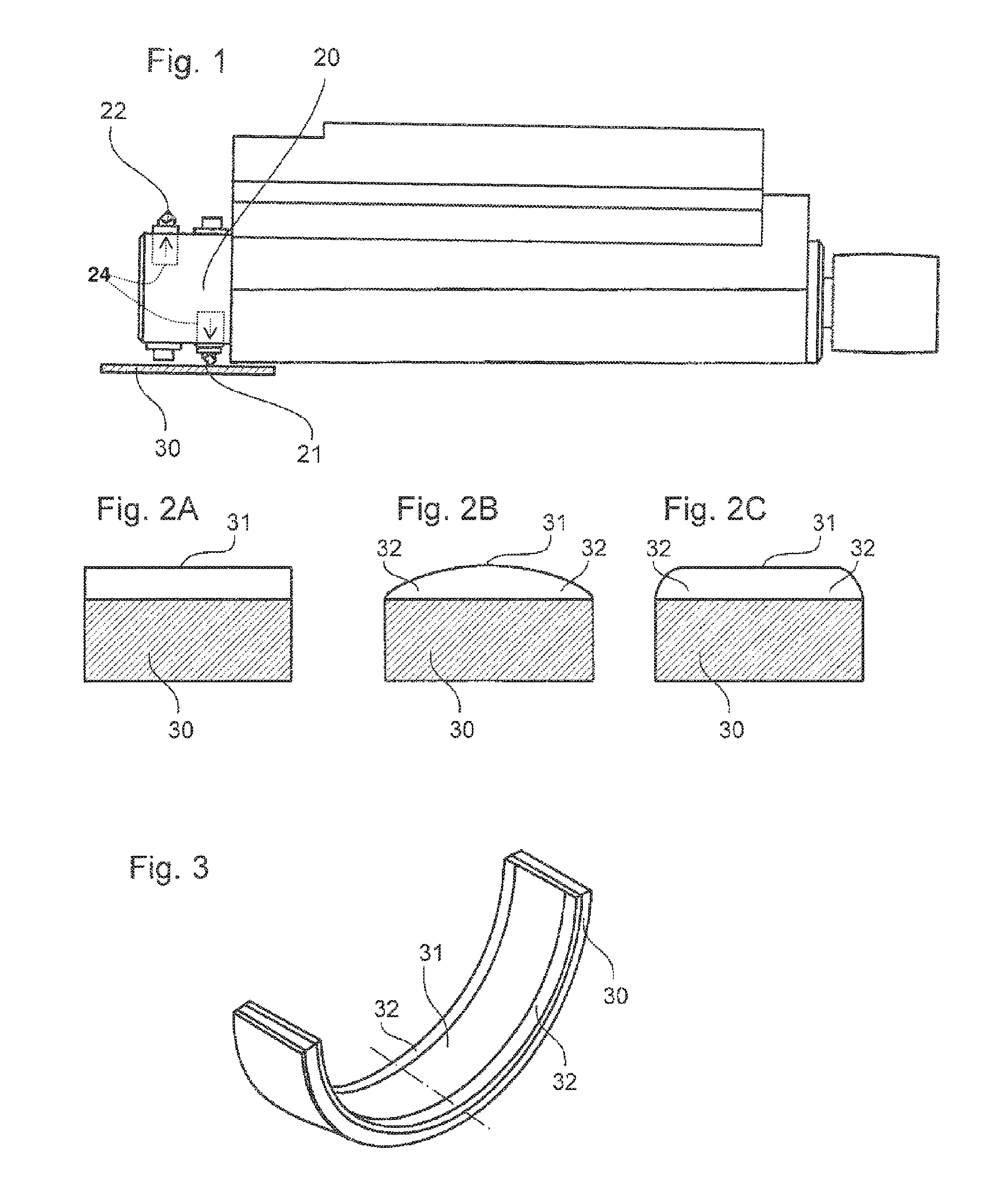
[0023]Described above with reference to FIG. 1 was a conventional tool for machining sliding surfaces of bearing shells. In an embodiment according to the invention, the cutting cartridge 21 is braced against a piezo element 24. By means of a corresponding actuation of the piezo element or piezo elements 24 (in the case of a plurality of cutting cartridges), this element expands and thus alters the axial position of the cutting cartridge, namely mainly in the radial direction relative to the drilling spindle 20.

[0024]When using the adjustable cutting cartridge, profiles of the bearing shell such as are shown in FIGS. 2B, 2C and 3 can, for example, be produced. Owing to the curvature in particular at the edge regions 32, also described as the exposed regions located at axial ends of the bearing shell, the effects on wear and running properties due to a bending or tilting of a shaft running under load in the bearing shell are lessened. Reference is made to the fact that the curvature ...


PUM

PropertyMeasurementUnit
thicknessaaaaaaaaaa
movementaaaaaaaaaa
rotational speedaaaaaaaaaa

Abstract

The invention relates to a tool for machining sliding surfaces of a bearing shell (30), comprising a rotary drive for driving a drilling spindle (20) that can be rotated about a rotational axis and at least one first cutting cartridge that is mounted on the drilling spindle (20) in order to cut the bearing shell (30) to a certain wall thickness by rotating the drilling spindle (20). The tool is characterized in that the first cutting cartridge can be adjusted by an adjustment means in a direction of adjustment that has a component in the radial direction of the drilling spindle, while the drilling spindle (20) is rotated by the rotary drive. The invention further relates to a bearing shell (30) comprising a deliberately structured sliding surface (31) and to a method for producing a bearing shell (30) comprising a deliberately structured sliding surface (31).

Description

BACKGROUND OF THE INVENTION[0001]1. Technical Field[0002]The present invention relates to a bearing shell having a structured sliding surface, to a tool for machining sliding surfaces of bearing shells, which comprises two cutting cartridges that are mounted on the spindle head of a drilling spindle, and to a method for machining a bearing shell using such a drilling spindle.[0003]2.Related Art[0004]The machining of sliding surfaces of bearing shells is nowadays implemented by means of a so-called drilling out of the bearing shells. A drilling spindle hereby rotates at a rotational speed X [rev / min] and moves at a feed rate Y [mm / rev] in the axial direction. Drilling out is implemented by means of a drilling spindle, inserted in the spindle head of which are two cutting cartridges lying opposite one another at 180°.[0005]A drilling spindle of this kind is shown in FIG. 1. The drilling spindle 20 comprises a first cutting cartridge 21 for cutting the bearing shell 30 to a certain wal...

Claims


Application Information

Patent Timeline
Patent Type & Authority Patents(United States)
IPC IPC(8): B23B29/034B23B41/12F16C33/14B23P13/02F16C33/02
CPCF16C33/02B23B29/034B23B29/03492B23B41/12B23P13/02F16C33/14B23B2260/108Y10T82/12Y10T82/125Y10T82/128Y10T408/03Y10T408/655F16C17/022F16C23/041F16C2220/60F16C2360/22
Inventor RITTMAN, STEFANROSSMANITH, RALFDOYLE, STEVEN
Owner FEDERAL MOGUL WIESBADEN
Why Eureka
Try Eureka