Beverage can

a can and beverage technology, applied in the field of cans, can solve problems such as the inability to communicate with data, and achieve the effects of simple positioning of the transponder, simple mechanical design, and good pivoting of the opening elemen

Inactive Publication Date: 2016-11-08
SEIBERSDORF LABOR
View PDF15 Cites 0 Cited by
  • Summary
  • Abstract
  • Description
  • Claims
  • Application Information

AI Technical Summary

Benefits of technology

[0022]A particularly simple mechanical design allowing good pivoting of the opening element with regard to the can provides that the opening element has a connecting element pivotable with regard to its body, which is connected to th...

Problems solved by technology

In any case, data communication is impossible as long as the open...

Method used


Image

  • Beverage can
  • Beverage can
  • Beverage can

Examples


first embodiment

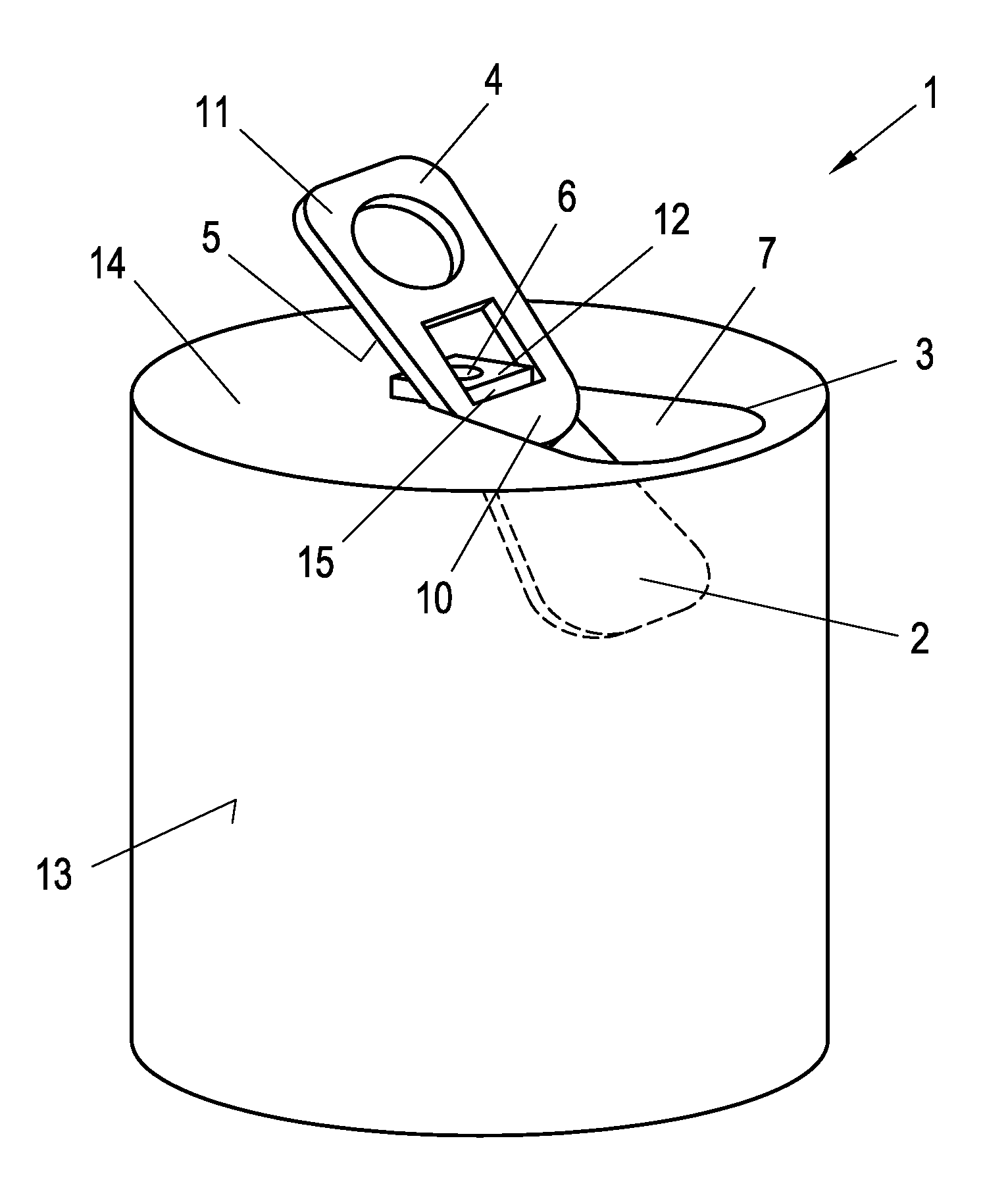
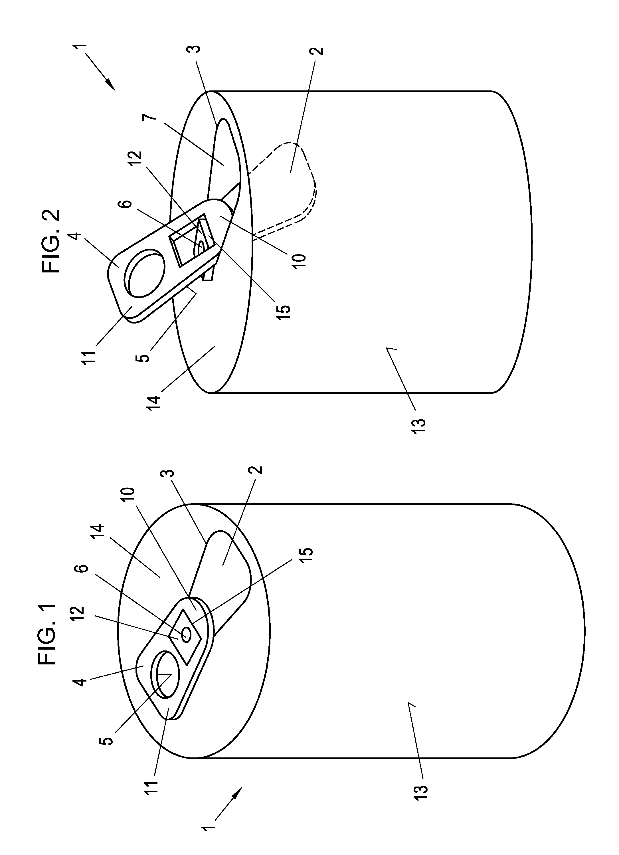
[0045]FIG. 1 shows a cylindrical can 1 according to the invention. The body of the can 1 completely consists of aluminum, wherein the can 1 can have a printed, decorative foil on its jacket surface 13. A sealing area 2 is provided on the front wall 14 of the can 1, which is demarcated by a predetermined breaking edge 3. In addition, the can 1 has an opening element 4, which is connected to the front wall 14 of the can 1 via a rivet passing through the recess 16 (FIG. 3) of the opening element 4. The opening element 4 has a connecting element 12 with the recess 16 pivotable with regard to its body, which is connected via rivet 6 to the front wall 14 of the can 1, is arranged in parallel with the front wall 14, and which in particular rests flatly against the front wall 14 of the can 1. Usually the opening element 4 can be pivoted around the rivet axis of the rivet 6, and in the present exemplary embodiment there is no connection of the opening element 4 to the can 1 that is rigid aga...

second embodiment

[0050]In the invention, the connection line 13, as shown in FIG. 5, is also arranged in a way that it rips when the opening element 4 is pivoted into the open position, which activates the antenna 8 or terminates its short-circuiting. As shown in FIG. 5, the connecting part 12 is conducting, wherein the connecting part 12 serves as part of the connection line 13. The other parts 13a, 13b of the connection line 13 are each connected with the connecting part 12 in an electrically conducting fashion via predetermined breaking points 17. FIG. 6 shows the area A (FIG. 5) of the predetermined breaking points 17 in detail.

third embodiment

[0051]In the invention, which is shown in FIG. 7, all electromagnetically active components, i.e. antenna 8, transponder chip 9 as well as connection line 13 including the predetermined breaking points 17, are arranged together on a foil 18 in the form of an adhesive label 18, wherein the adhesive label 18 is adhered to the opening element 14. The electric connection line 13 can be arranged within or on the adhesive label 18. The connection line 13 and the foil 18 are partly arranged on the opening element 4 and partly on the connecting element 12. The adhesive label 18, which is shown from above in FIG. 8, has in the area between the connecting element 12 and the body of the opening element 4, in particular at the predetermined breaking points 17, a perforated edge 19, which rips when the opening element 4 is pivoted and also allows for ripping of the connection line 13 at the predetermined breaking points 17.


PUM


Abstract

A can includes a body, a sealing area on a wall delimited by a breaking edge, an opening element which in an initial position abuts the wall and is connected to the wall by a connecting element of the opening element. Pivoting the opening element into an open position tears the sealing area along the breaking edge and forms an emptying opening in a region delimited by the breaking edge. The opening element has a carrier body of electrically and/or magnetically insulating material, the opening element carries an antenna on or in the carrier body and a transponder chip connected to the antenna. An electric connection line electrically conductively interconnects and short-circuits terminals of the antenna in the initial position. The electric connection line is irreversibly interrupted and activates the antenna when opening the can by pivoting the opening element from the initial to the open position.

Description

BACKGROUND OF THE INVENTIONField of the Invention[0001]The invention relates to a can comprising a body, in particular of aluminum, a sealing area at least partially demarcated on a front wall of the can by a predetermined breaking edge, an opening element which in its initial position rests at least partially against the front wall of the can and is connected to the front wall at least at one point via a connecting element, which is formed as part of the opening element, and is in particular connected to the front wall, wherein when the opening element is pivoted with regard to the can from the initial position to an open position, the sealing area rips along the predetermined breaking edge and an opening for emptying the content of the can is formed in the intermediate area demarcated by the predetermined breaking edge.[0002]A plurality of beverage cans is known from the state of the art, which can be opened by means of a one-time seal, where a sealing area is broken out of the bo...

Claims


Application Information

Patent Timeline
IPC IPC(8): B65D17/00B65D51/24
CPCB65D17/165B65D51/245B65D2203/10B65D2517/0014B65D2517/0053B65D17/00G06K19/0775H01Q1/2225B65D17/4012
Inventor SCHMID, GERNOT
Owner SEIBERSDORF LABOR
Why Eureka
Try Eureka