Stopper for a bottle and sealing element for said stopper

a technology for sealing elements and stoppers, which is applied in the direction of closing stoppers, application, rotating screw stoppers, etc., can solve the problems of inability to achieve proper sealing any longer once, inability to reattach generally, and inability to achieve proper sealing once again, etc., to achieve sufficient sealing of the stopper in the bottle for transportation and/or

Inactive Publication Date: 2016-11-15
PATENT ROOM P5 S A R L
View PDF20 Cites 28 Cited by
  • Summary
  • Abstract
  • Description
  • Claims
  • Application Information

AI Technical Summary

Benefits of technology

[0014]It is therefore the object of the invention to provide a closure system for a bottle that overcomes any or all of the above-mentioned drawbacks of the systems known from EP 1 451 081 B1, EP 1 456 092 B1, GB 1 276 485, GB 26,631 and U.S. Pat. No. 3,245,569. In particular, it is an object of the invention to provide a closure system for a bottle which allows making the sealing of the stopper in the bottle sufficiently strong for transportation and / or storage of the bottle at a high temperature and / or in horizontal position even in the absence of a fixing element attached to the bottle body. Further, it is an object of the invention to provide a closure system for a bottle which can be used with bottles ordinarily used by producers for bottling their products, without requiring a specific bottle. Further, it is an object of the invention to provide a closure system which allows for an inexpensive process of sealing the bottle in the bottling plant. Further, it is an object of the invention to provide a tamper proof mechanism which can be used in the absence of a capper or the like on top of the stopper. Further, it is an object of the invention to provide a bottle to overcome the drawbacks of the prior art systems associated with a gap between the stopper and the bottle caused by the sealing element.

Problems solved by technology

First of all, the fixing element attached to the bottle body comes at additional costs.
Secondly, once the detachable fixing element is removed, e.g. when the bottle is opened for the first time, it can in general not be reattached.
Therefore, proper sealing cannot be achieved any longer once the bottle has been opened.
As a consequence, it cannot be stored any more, e.g., in horizontal position.
Thirdly, if the fixing element inadvertently comes off, for instance during transport, the stopper is not mechanically retained anymore and may easily come off as a result of increased internal bottle pressure.
Moreover, the closure systems disclosed in EP 1 451 081 B1 and EP 1 456 092 B1 present another drawback, when used in the wine industry for closing a wine bottle.
Indeed, since the closure systems cannot cope with the manufacturing tolerances of ordinary wine bottles, these closure systems require a specific wine bottle, the mouth of which is specifically adapted to the shape and dimensions of the stopper.
Therefore, wine producers wishing to adopt such a closure system for sealing their wine bottles instead of corks made of natural or synthetic cork will be forced to change their bottling processes and adapt them to these specific bottles, which are more expensive than standard bottles and are also only available from a few glass bottle manufacturers.
The bottle stopper arrangement cannot be easily adapted to any bottle, for instance a bottle having a cylindrical bottle neck.
Further, when the stopper is removed from the bottle, the insert stays on the bottle, which makes use of the bottle unpleasant.
The need for two steps makes bottling expensive.
Further, the user needs to rotate the stopper over several turns before completely unscrewing the stopper, which makes the opening process cumbersome.
However, the stopper disclosed in GB 1 276 485 has various drawbacks such as for the process of sealing, it is required that the stopper is placed in the bottle and rotated since it would not be possible to insert an already assembled and sealed stopper due to its large sleeve and increased displacement at the lower part.
This need for two steps makes bottling expensive.
However one drawback of this stopper is that the sheath is provided in the entire surface of the core, thereby requiring the core to be placed on the sheath inside the bottle and then rotated.
This requirement of rotation during bottling makes the bottling method expensive.
Another drawback of the system in the above prior art documents having a sealing element between the stopper and the bottle such as in GB 1 276 485 and GB 26 631 is that a gap formed between the stopper and the bottle due to the placement of the sealing element.
This gap creates accumulation of dirt and dust and therefore causes unhygienic circumstances.
Furthermore, none of the closure systems without a capper or the like on the top of the stopper such as U.S. Pat. No. 3,245,569, GB 1 276 485 or GB 26 631 have any indication provided to the user if the stopper has been used earlier and if the bottle has been opened after bottling, since it does not have a tamper proof mechanism.

Method used


Image

  • Stopper for a bottle and sealing element for said stopper
  • Stopper for a bottle and sealing element for said stopper
  • Stopper for a bottle and sealing element for said stopper

Examples


first embodiment

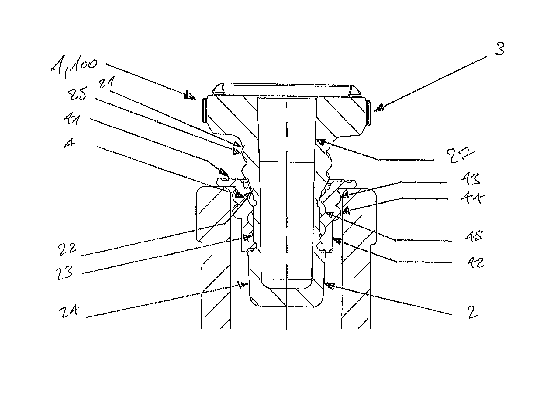
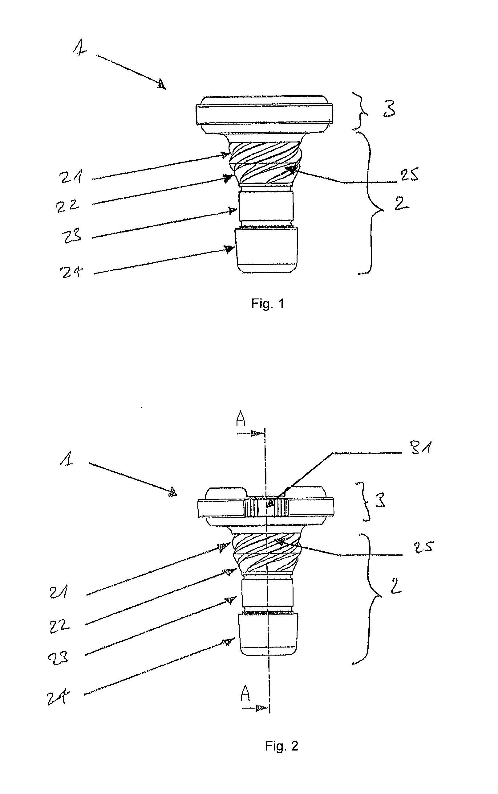
[0233]FIG. 1 shows a side view of a stopper 1 for a bottle according to the invention. The stopper 1 comprises a stopper part 2 for introduction into a mouth of a bottle and a head part 3 joining the stopper part 2 via a neck portion. The head part 3 of the stopper 1 may be defined in general terms as the part of the stopper 1 protruding out of the mouth of the bottle when the bottle is sealed by the stopper 1. The neck portion may be defined in general terms as the part of the stopper 1 where the head part 3 joins the stopper part 2. The neck portion therefore represents a transition part of the stopper 1 between the head part 3 and the stopper part 2. The neck portion extends a certain distance on the stopper part 2 away from the head part 3. Therefore, the neck portion does not only comprise the portion of the stopper part 2 which is located directly under the head part 3.

[0234]In the exemplary embodiment represented with respect to FIG. 1, the neck portion may start with the cur...

second embodiment

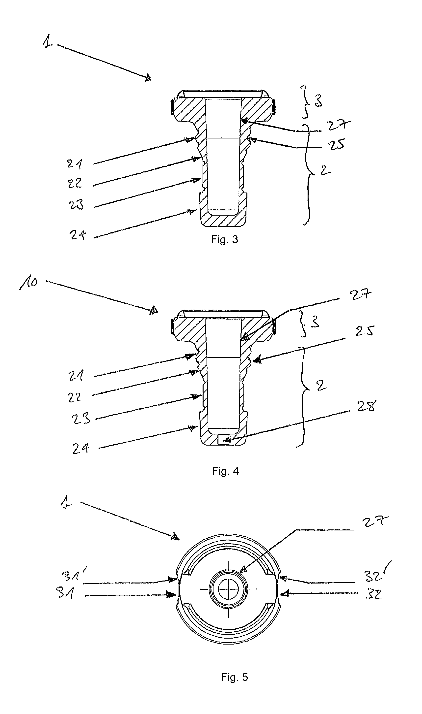
[0252]FIG. 6 shows a perspective cross-sectional view of a stopper 10 for a bottle according to the invention. FIG. 61 reveals the inside of the stopper 10 and, in particular, the inside walls of the longitudinal cavity 27. It further shows the opening 28, out of which the longitudinal cavity 27 opens out from the stopper 10.

[0253]FIG. 7 shows a perspective cross-sectional view of a stopper 100 for a bottle according to a third embodiment of the invention. The stopper 100 for a bottle according to the third embodiment of the invention differs from the stopper 10 for a bottle according to the second embodiment in that no opening is provided at the tip of the stopper part 2, so that the longitudinal cavity 27 does not open out at the tip of the stopper part 2. The longitudinal cavity 27 therefore only opens out at the upper surface of the head part 3, as apparent from FIG. 7.

[0254]As it will be appreciated by the skilled person, the stopper with a longitudinal cavity as described abov...

fifth embodiment

[0293]FIG. 14 shows a side view of a stopper 300 for a bottle according to the invention. FIG. 14 shows a longitudinal cavity 27 in solid lines, which represents a longitudinal cavity 27 formed within the stopper 300. The longitudinal cavity 27 extends along the longitudinal axis of the stopper 300 from an upper surface of the head part 3 up to a bottom located within the stopper 300.

[0294]FIG. 15 shows a side view of the stopper 200, 300 for a bottle according to a fourth or fifth embodiment of the invention with a sealing element 4 according to an embodiment of the invention that is arranged on the stopper part 2 of the stopper 200, 300. The sealing element 4 is shown in an intermediate position in the process of being brought from the sealed position to the unsealed position by the user.

[0295]FIG. 16 shows a side view of the stopper 200, 300 as represented in FIG. 15 in a later stage of the process of bringing the sealing element into the unsealed position. FIG. 16 shows that the...


PUM


Abstract

A stopper for a bottle and a sealing element for sealing the stopper in the mouth of the bottle, which is separate from the bottle. The stopper comprises a stopper part for introduction into a mouth of the bottle, and a head part for remaining outside the mouth of the bottle, the head part having a diameter that is larger than that of the stopper part, wherein the stopper part comprises a an interlocking mechanism for engaging with a counterpart interlocking mechanism of the sealing element. The sealing element is forced against an inner wall of the mouth, thereby being brought into a sealed position, upon introducing the stopper part into the mouth, in which sealed position the stopper is held on the bottle. The interlocking mechanisms permit bringing the sealing element into an unsealed position by an unsealing action which comprises rotating the stopper with respect to the bottle.

Description

FIELD OF THE INVENTION[0001]The invention relates to a stopper for a bottle, preferably a beverage bottle, like a wine bottle, and a sealing element for sealing a stopper for a bottle. The invention further relates to a method of sealing a bottle.BACKGROUND OF THE INVENTION[0002]A sealable bottle is known from the European patents EP 1 451 081 B1 and EP 1 456 092 B1. A bottle disclosed in these patents comprises a stopper which is made of glass and can be inserted into the bottle opening. The bottle further comprises a fixing element that is attached to the bottle body in a detachable manner and retains the stopper inserted in the bottle opening in place.[0003]Such a bottle presents several drawbacks. First of all, the fixing element attached to the bottle body comes at additional costs. Secondly, once the detachable fixing element is removed, e.g. when the bottle is opened for the first time, it can in general not be reattached. Therefore, proper sealing cannot be achieved any long...

Claims


Application Information

Patent Timeline
Patent Type & Authority Patents(United States)
IPC IPC(8): B65D39/08B65D39/12B67B1/06B65D39/00
CPCB65D39/082B65D39/0047B65D39/0064B65D39/12B67B1/06B65D2539/006B65D39/0094B65D51/1616B65D51/28B65D55/02
Inventor LEDUN, AUDREYLANGELAAN, PIETER HENDERIKUSHELMIG, REINHARD JOSEF
Owner PATENT ROOM P5 S A R L
Why Eureka
Try Eureka