
Backstopping clutch with torque transmission through radial surface of outer race

a technology of torque transmission and outer race, which is applied in the direction of automatic clutches, freewheel clutches, mechanical equipment, etc., can solve the problems of difficult adaptation to various drive trains, and achieve the effects of increasing friction, high heat conductivity, and relatively stable coefficient of friction

Active Publication Date: 2016-11-15
STIEBER GMBH
View PDF15 Cites 0 Cited by
  • Summary
  • Abstract
  • Description
  • Claims
  • Application Information

AI Technical Summary

Benefits of technology

[0010]A backstopping clutch in accordance with the present invention may offer several advantages. The inventive clutch is able to transmit a relatively large braking torque despite a relatively small size. The inventive clutch also has a relatively high level of heat conductivity for increased friction. Axial loading on the outer race is independent of wear on the friction discs, temperature expansion and manufacturing tolerances. The coefficient of friction is also relatively stable over the life of the clutch and can be adjusted to fit the needs of the operator. The outer race can be centered using caged roller bearings that are more robust and / or smaller than bearings in conventional clutches. The design of clutch is also easily adaptable to various drive trains. Finally, the reduced heat generated by the clutch as compared to conventional clutches permits increased slip times thereby enabling improved dampening of vibrations in conveyors and similar systems resulting from sudden failures of the motor or other drive components. Slip times are also subject to greater control through the use of different materials in the friction discs and lubricants as opposed to control through spring force as in conventional clutches.

Problems solved by technology

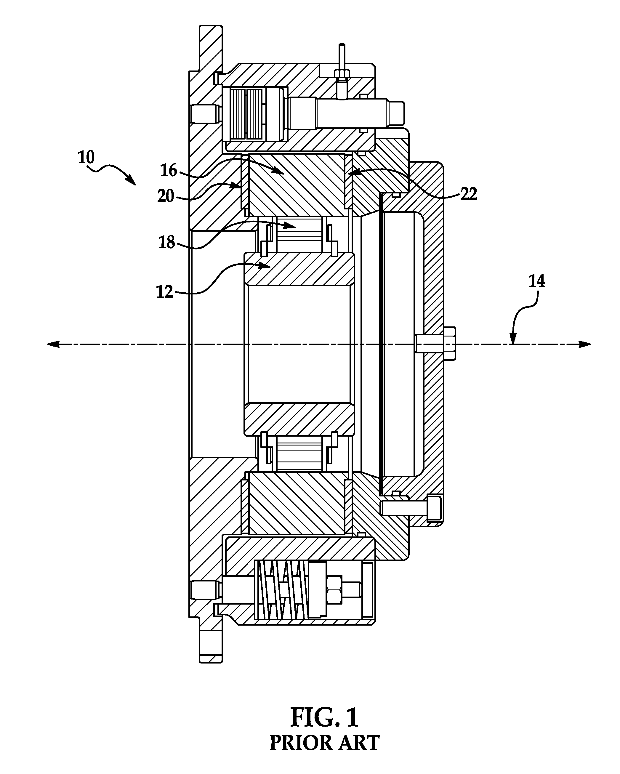
The design of clutch 10 also makes it difficult to adapt to various drive trains.
Finally, the relatively high heat generated by the clutch limits the time that the clutch can slip which lessens its ability to dampen longitudinal vibrations along a conveyor resulting from a sudden failure of the motor or related components.

Method used


Image

  • Backstopping clutch with torque transmission through radial surface of outer race
  • Backstopping clutch with torque transmission through radial surface of outer race
  • Backstopping clutch with torque transmission through radial surface of outer race

Examples


Embodiment Construction

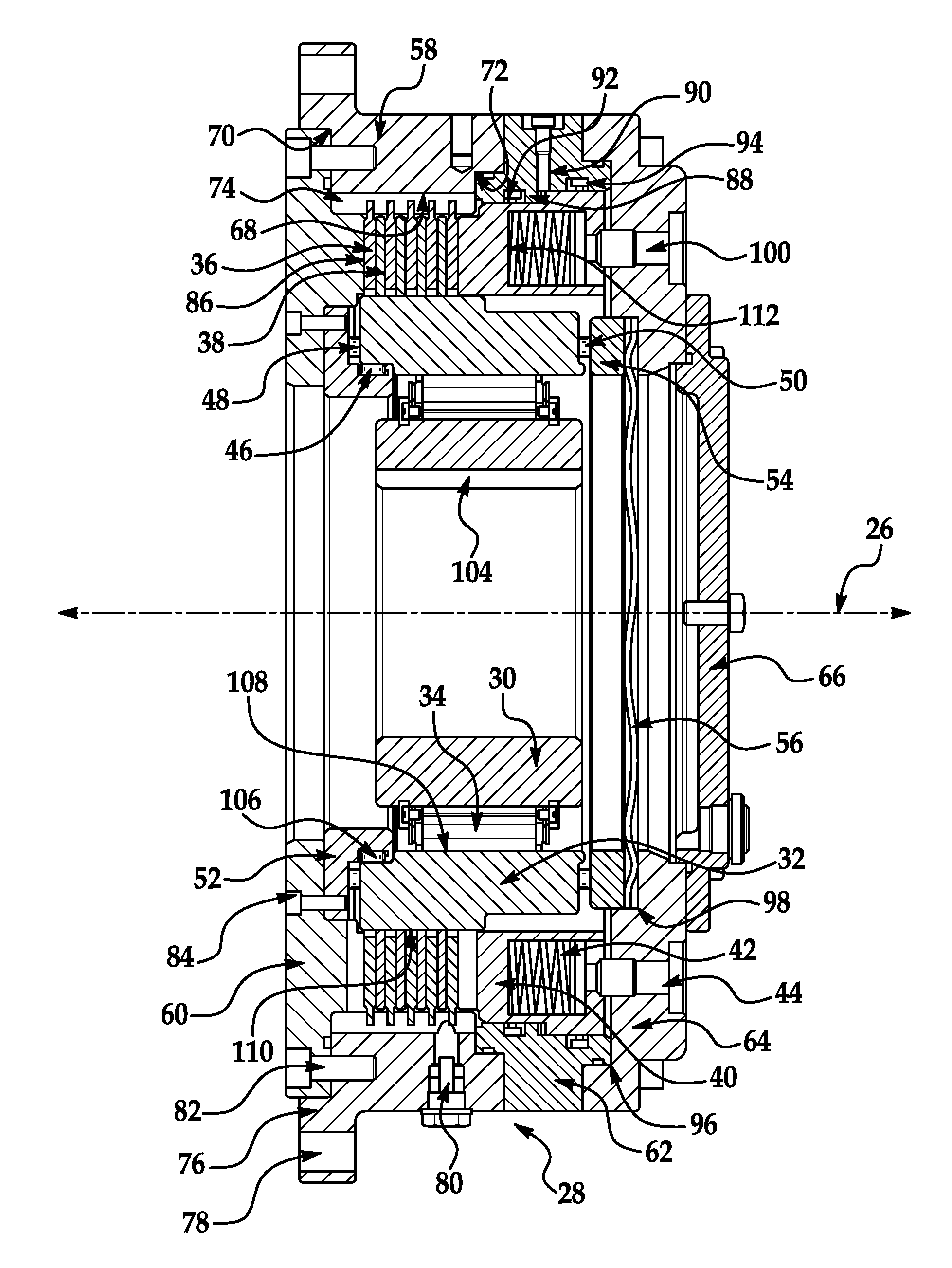
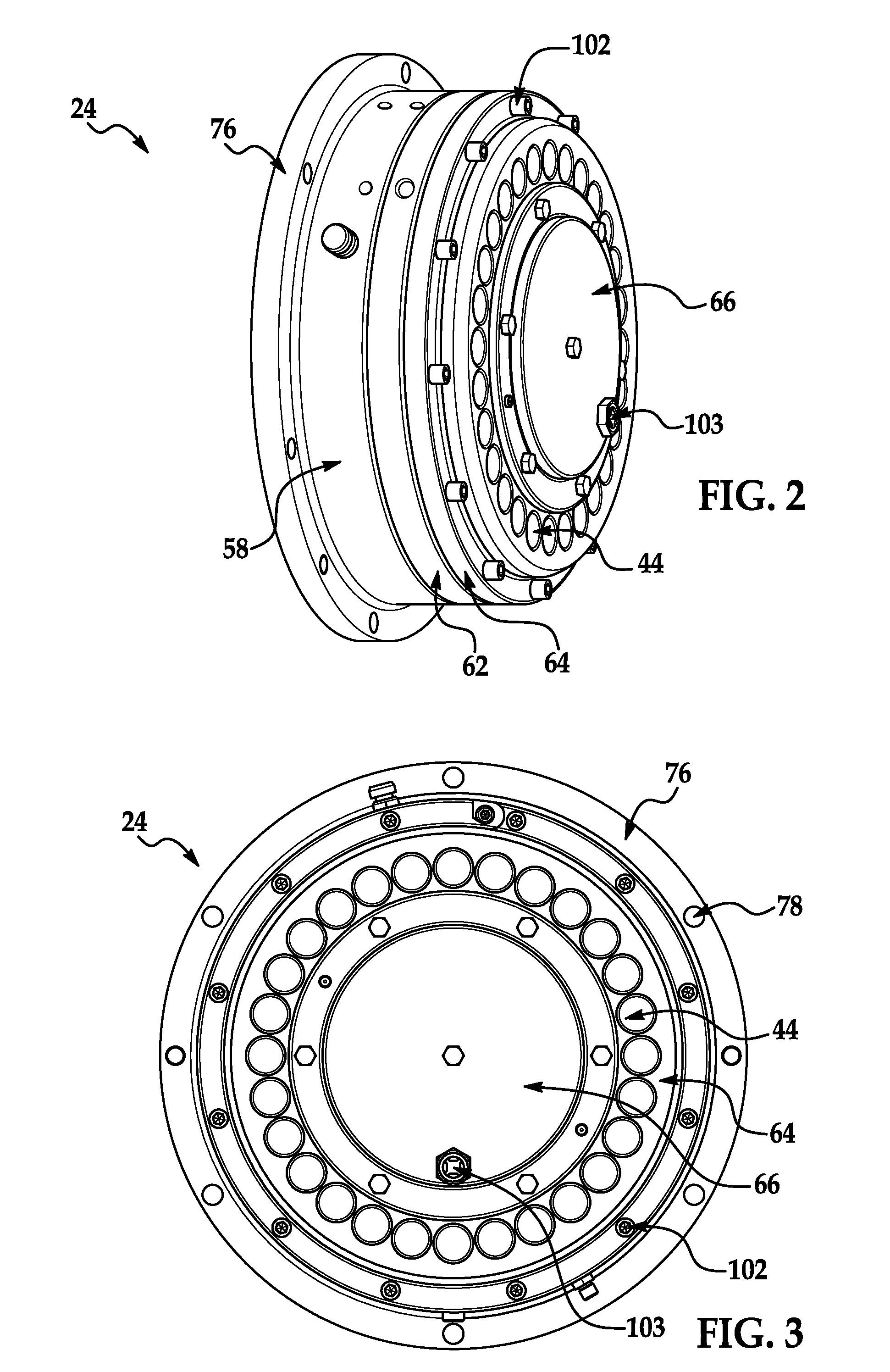
[0016]Referring now to the drawings wherein like reference numerals are used to identify identical components in the various views, FIGS. 2-4 illustrate a backstopping clutch 24 in accordance with one embodiment of the invention. Clutch 24 is provided to inhibit reverse rotation of a driven shaft (not shown) about a rotational axis 26 and damping of longitudinal vibrations in the drive train due to slipping of the brake. Clutch 24 may include a housing 28, inner race 30, outer race 32, torque transmission members 34, friction discs 36, 38, means, such as piston 40 and springs 42, for urging discs 36, 38, into engagement, means, such as adjusters 44, for adjusting the tension on springs 42 and, therefore, the friction force in clutch 24, bearings 46, 48, 50, bearing rings 52, 54, and spring 56.

[0017]Housing 28 provides a path for reacting the torque from engagement of clutch 24. Housing 28 also provides structural support to the other components of clutch 24 and protects those compon...


PUM


Abstract

A backstopping clutch is provided having improved torque transmission. The clutch includes a housing, an inner race disposed within the housing and configured for coupling to a driven member for rotation about a rotational axis and an outer race disposed with the housing radially outwardly of the inner race. A plurality of torque transmission members are disposed between the inner and outer races such that the inner race is freely rotatable relative to the outer race in a first rotational direction, but the torque transmission members engage the inner and outer races and inhibit rotation of the inner race relative to the outer race in a second rotational direction. Friction discs are coupled to a radially inner surface of the housing and a radially outer surface of the outer race and configured to engage one another to transmit a braking torque.

Description

BACKGROUND OF THE INVENTION[0001]a. Field of the Invention[0002]This invention relates to backstopping clutches. In particular, the instant invention relates to a backstopping clutch in which a braking torque is transmitted through a radial surface of the outer race to permit improved torque transmission while also reducing the size of the clutch.[0003]b. Background Art[0004]In many motor driven systems, it is desirable to prevent or limit movement of system components in one direction. For example, mining operations typically use inclined conveyors to convey material to a surface location or other outlet. It is desirable to prevent or limit reverse movement of the conveyor in the event of a loss of power or a failure of a driveline component such as a motor, gearbox or coupling in order to prevent material from moving backwards on the conveyor and causing damage to the system and significant injuries to personnel operating the system.[0005]Backstopping clutches are frequently used ...

Claims


Application Information

Patent Timeline
Patent Type & Authority Patents(United States)
IPC IPC(8): F16D43/02F16D41/06F16D67/02F16D55/38F16D59/00F16D127/00
CPCF16D67/02F16D41/06F16D55/38F16D59/00F16D2127/004
Inventor KRETSCHMER, TORSTENVILLWOCK, FRANK
Owner STIEBER GMBH
Learn More