Crimping tool for wire end ferrules

a crimping tool and wire end technology, applied in the direction of pliers, line/current collector details, electrical equipment, etc., can solve the problem of limited diameter range of wire end ferrules, and achieve the effect of reducing mechanical stress on the end point, reducing the diameter range, and facilitating the passage of wire end points

Active Publication Date: 2016-11-15
WEIDMULLER INTERFACE GMBH & CO KG
View PDF18 Cites 6 Cited by
  • Summary
  • Abstract
  • Description
  • Claims
  • Application Information

AI Technical Summary

Benefits of technology

[0012]The part of the cascade spring, that is part of the base sheet, is preferably realized by a slot contained in the base sheet, which slot runs substantially parallel to the outer contour of the base sheet. In order to reduce the mechanical stress on the end point of the notch, the end point of the notch is designed to be rounded. The contour of the notch advantageously runs around the articulation bolt and exits out of the base sheet on the upper side of the handle. Therefore, the spring obtains a geometry substantially in the form of a leaf spring shaped like an arch or circular segment. In order to realize a significant spring path, the notch is preferably designed to be appropriately long and wide. Therefore, the spring realized in this manner lies outside of the handle. Therefore, a parallel connection of both springs results by the arrangement of the notch in both of the side base sheets of the frame.
[0013]The crimping elements preferably have circular blind holes on their side surfaces by which the crimping stamps are rotatably supported on bearing pins on the base sheets. The non-through counter-bored bearing pins of the crimping elements advantageously result in a correspondingly greater carrying cross section of the crimping stamp so that the crimping elements have elevated mechanical load properties compared to comparable constructions with through bearing pins.
[0014]Furthermore, the sliding piece plate preferably has a peroration in the form of a recessed hexagonal round profile in which sliding pieces are rotatably mounted and transfer the drive force resulting from the toggle joint kinematics onto the crimping stamps. A radial longitudinal compensation for the crimping elements is made possible by a groove in the slide pieces which provide compensation by the pivotal movement of the crimping elements. The advantage of this solution lies in a flat contact, and therefore in a reduced local surface pressure between sliding piece and crimping stamps over the entire activation path.
[0015]For an optimized pressing and a reduction of fracture of the crimped wire end ferrules, the crimping elements advantageously have a corrugated contour on the active stamping surface. A sharp-edged construction such as, e.g., triangular or quadratic contours on the active stamping surface would leave, in comparison, a sharp-edged impression on the finished, crimped wire end ferrule that would increase the sensitivity to fracture of the crimped wire end ferrules. In order to prevent a clamping of wire end ferrules with a rather small cross section between the crimping stamps, the contour of the active stamping surface is advantageously constructed in such a manner that adjacent crimping stamps merge into one another in a contour-congruent manner.
[0016]The contour of the active stamping surface is furthermore designed in such a manner that, given the appropriate positioning of the wire end ferrule into the crimping die on the end of the wire end ferrule, an introductory slope is produced that facilitates the introduction of the wire end ferrule into a clamping system.

Problems solved by technology

However, the force path compensation device realized in this manner allows only a very limited diameter range of wire end ferrules that can be pressed in the pressing tongs.

Method used


Image

  • Crimping tool for wire end ferrules
  • Crimping tool for wire end ferrules
  • Crimping tool for wire end ferrules

Examples


Embodiment Construction

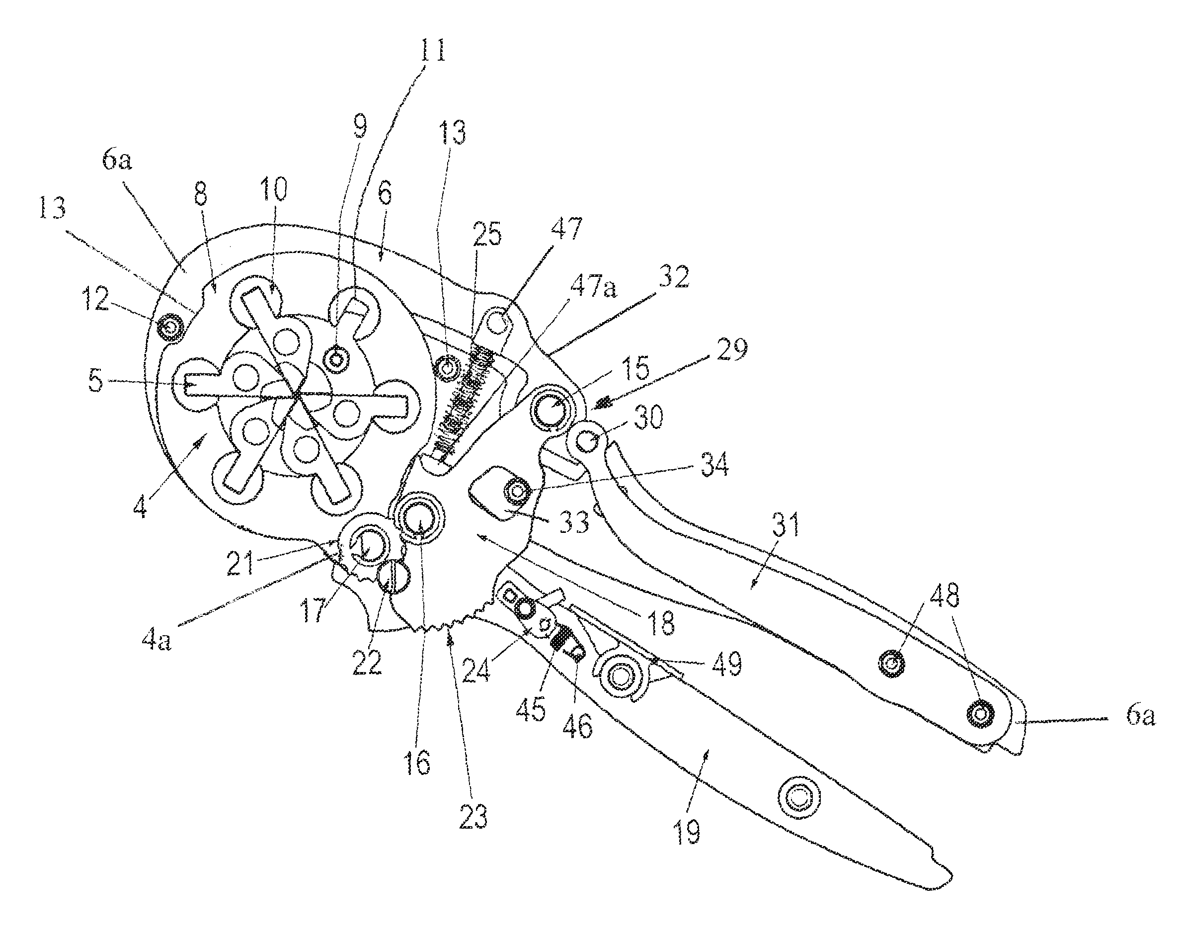
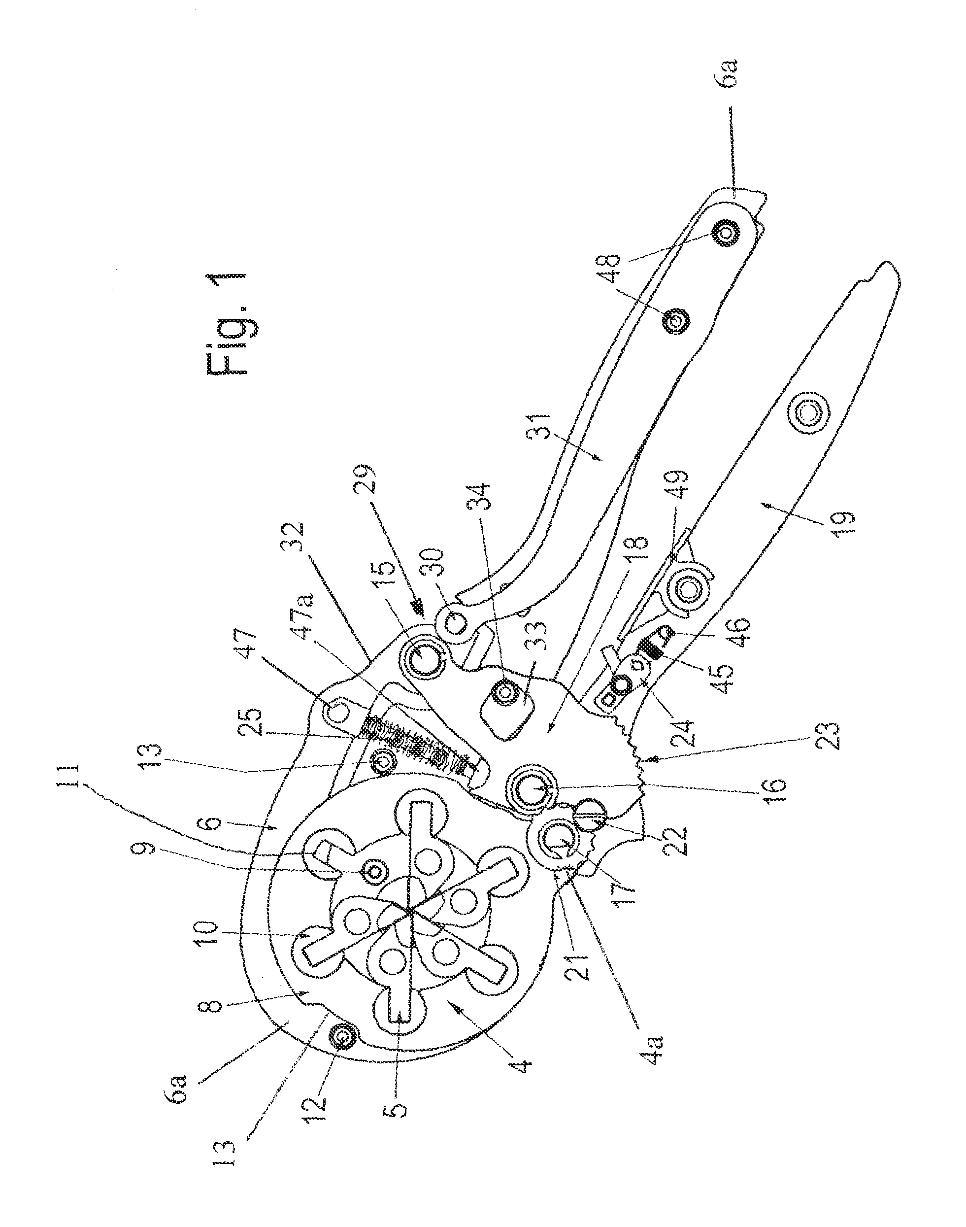
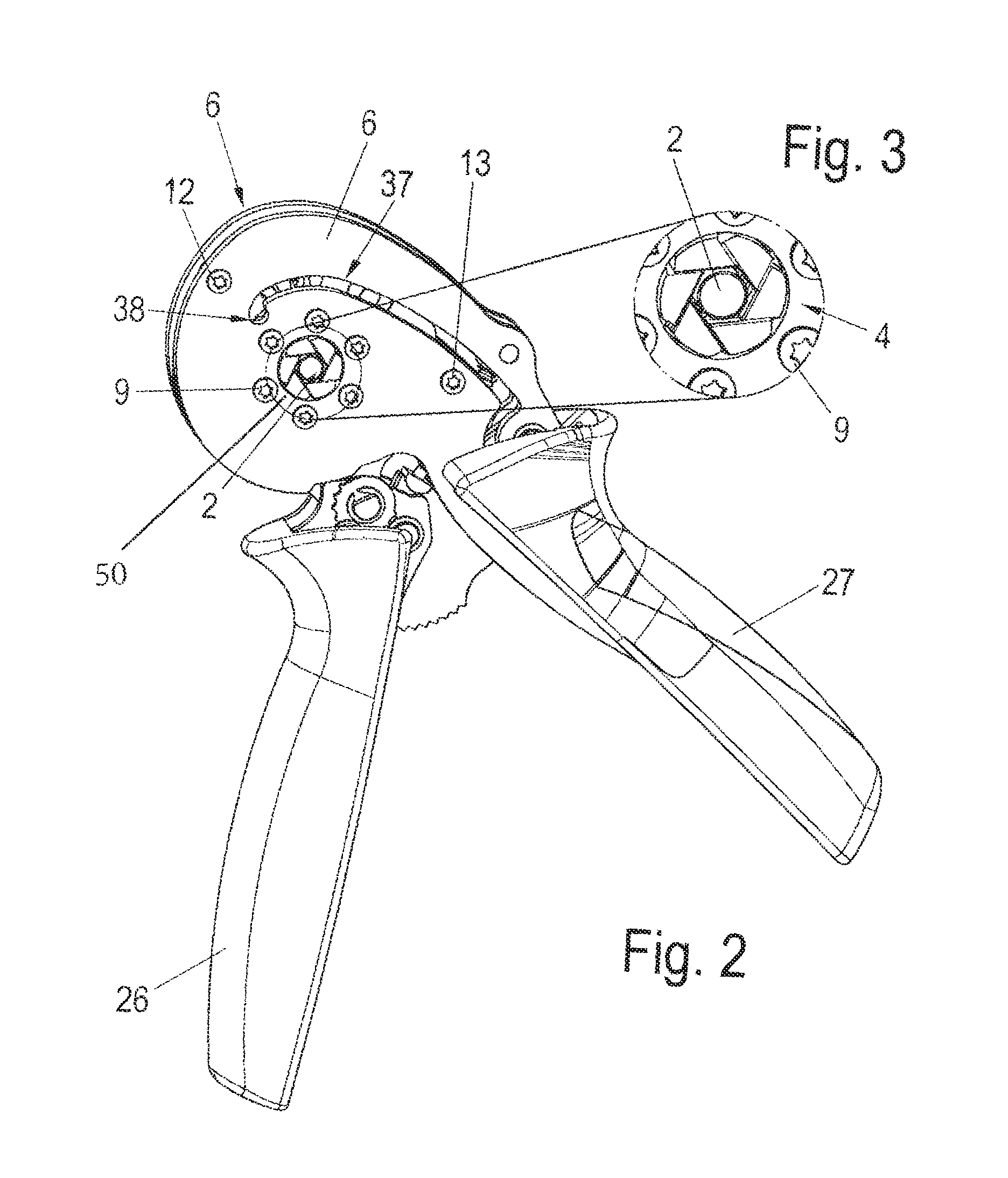
[0033]Referring first more particularly to FIGS. 1-3, the crimping tool 1 of the present invention is designed to crimp female contacts, cable terminals or the like on electrical conductors 3. The manually operated crimping tool 1 in the form of tongs comprises a crimping die 4 with automatic adjustment to the crimping ferrule cross section and the conductor cross section to be worked that is formed from several crimping stamps 5. The pressed wire end ferrule 2 can be constructed in particular in a hexagonal or quadratic shape. The crimping tool includes a pair of parallel spaced side plates 6 that are formed from a resilient metal material, such as spring steel. The side plates have parallel lever portions 6a that extend from base body portions 6b containing opposed access openings 50 (FIG. 2), thereby to define a first operating lever. The side plates are connected by bolt and spacer means 12 and 13. Rotatably mounted for angular displacement between the side plate body portions 6...


PUM

PropertyMeasurementUnit
forceaaaaaaaaaa
resilientaaaaaaaaaa
sizeaaaaaaaaaa

Abstract

A scissors-type crimping tool for crimping a female contact onto an electrical conductor, comprising a planar base member having body and first lever portions; an annular crimping die member connected for rotation between die-open and die-crimping positions relative to the base member body portion; a toggle link arrangement connecting a second lever for pivotal movement relative to the base member body portion; and a cascade spring arrangement operable by the toggle arrangement from a non-stressed condition to a stressed caged condition during initial movement of the second lever in the closed direction, and to a stressed condition during further movement of the second lever, thereby to afford processing of different cross-sections of ferrules and conductors in the crimping die, and to apply the force of the stressed cascade spring arrangement to the crimping die member during the final stage of the crimping operation.

Description

REFERENCE TO RELATED APPLICATIONS[0001]This application is a national stage application under 35 C.F.R. §371 of the PCT International Application No. PCT / EP2013 / 062079 filed Jun. 12, 2013, which claims priority of the German application No. DE 20 2012 102 561.2 filed Jul. 11, 2012.BACKGROUND OF THE INVENTION[0002]Field of the Invention[0003]A scissors-type crimping tool is provided for crimping a female electrical contact onto an electrical conductor, including a toggle arrangement actuated by an operating lever to operate cascade spring means from a non-stressed condition to a stressed caged condition, thereby to afford processing of different cross-sections of ferrules and conductors in the crimping die, and to apply the force of the stressed cascade spring arrangement to the crimping die member during the final stage of the crimping operation.[0004]Description of Related Art[0005]Crimping tools are known from the prior art, as shown by the German patent No. DE 195 07 347 C1, whic...

Claims


Application Information

Patent Timeline
Patent Type & Authority Patents(United States)
IPC IPC(8): B25B7/06H01R43/042B25B7/12
CPCH01R43/0428B25B7/06B25B7/123H01R43/0424Y10T29/53226
Inventor DIERKS, CHRISTOPHHANNING, GUENTHERHETLAND, DETLEVKELLER, DAVID
Owner WEIDMULLER INTERFACE GMBH & CO KG
Why Eureka
Try Eureka