Pull tab and method of manufacturing a pull tab

a pull tab and pull tab technology, applied in the field of pull tabs, can solve the problems of inability to easily slide the zipper, the manufacturing process is expensive and time-consuming, and the metal plate is often too small to allow for easy sliding of the zipper, so as to avoid excess flashing

Inactive Publication Date: 2016-11-22
DURAFLEX HONG KONG
View PDF18 Cites 4 Cited by
  • Summary
  • Abstract
  • Description
  • Claims
  • Application Information

AI Technical Summary

Benefits of technology

[0005]It is therefore an object of the invention to provide a zipper pull that can be applied directly to the zipper head, can be customized for a variety of sizes and decorations, and which can be produced simply and economically.
[0011]The plug and socket have corresponding shapes, so that the plug fits securely within the socket. In one embodiment, the plug has a plurality of grooves and the socket has a plurality of protrusions corresponding to the grooves. This way, the protrusions prevent the plug from exiting the socket, even under force. In another embodiment, the plug and socket have a trapezoid shape. The wider end of the trapezoid is placed facing the direction of force, so that the plug cannot be inadvertently pulled out of the socket. Any other suitable set of corresponding shapes could be molded for the plug and socket as well.
[0012]The pull tab of the present invention can be applied directly to a zipper head without the need for a traditional zipper pull. This reduces cost and labor in manufacturing consumer items. The cord could be made to any desired length, depending on the needs of the end user.
[0013]The method for manufacturing the pull tab described above eliminates waste and labor by using a continuous molding process for a large number of pull tabs. Traditionally, each length of cord was required to be cut, the ends burned, and then individually molded onto the pull tab. In the present invention, a mold is used that has a mold cavity corresponding to a plug and a cord retaining member connected to each other. The cord is fed in from a reel so that the cord extends through the mold cavity. A channel can be made in the mold outside the mold cavity for the cord. Mold material is then injected into the mold cavity to form molded components around the cord. After the cord with the molded components is removed from the mold, the molded components are cut at a predetermined cutting point to form a cord having a cord retaining member on one end and a plug on the other.
[0015]The cutting of the components preferably occurs using a heated knife. This avoids any excess flashing being left on the molded components.

Problems solved by technology

These metal plates are often too small to allow for easy sliding of the zipper.
This is especially true when the zipper pull becomes wet and slippery.
However, these additional cords are often too long to make pulling easy, and the manufacturing process is expensive and time consuming.

Method used


Image

  • Pull tab and method of manufacturing a pull tab
  • Pull tab and method of manufacturing a pull tab
  • Pull tab and method of manufacturing a pull tab

Examples


Embodiment Construction

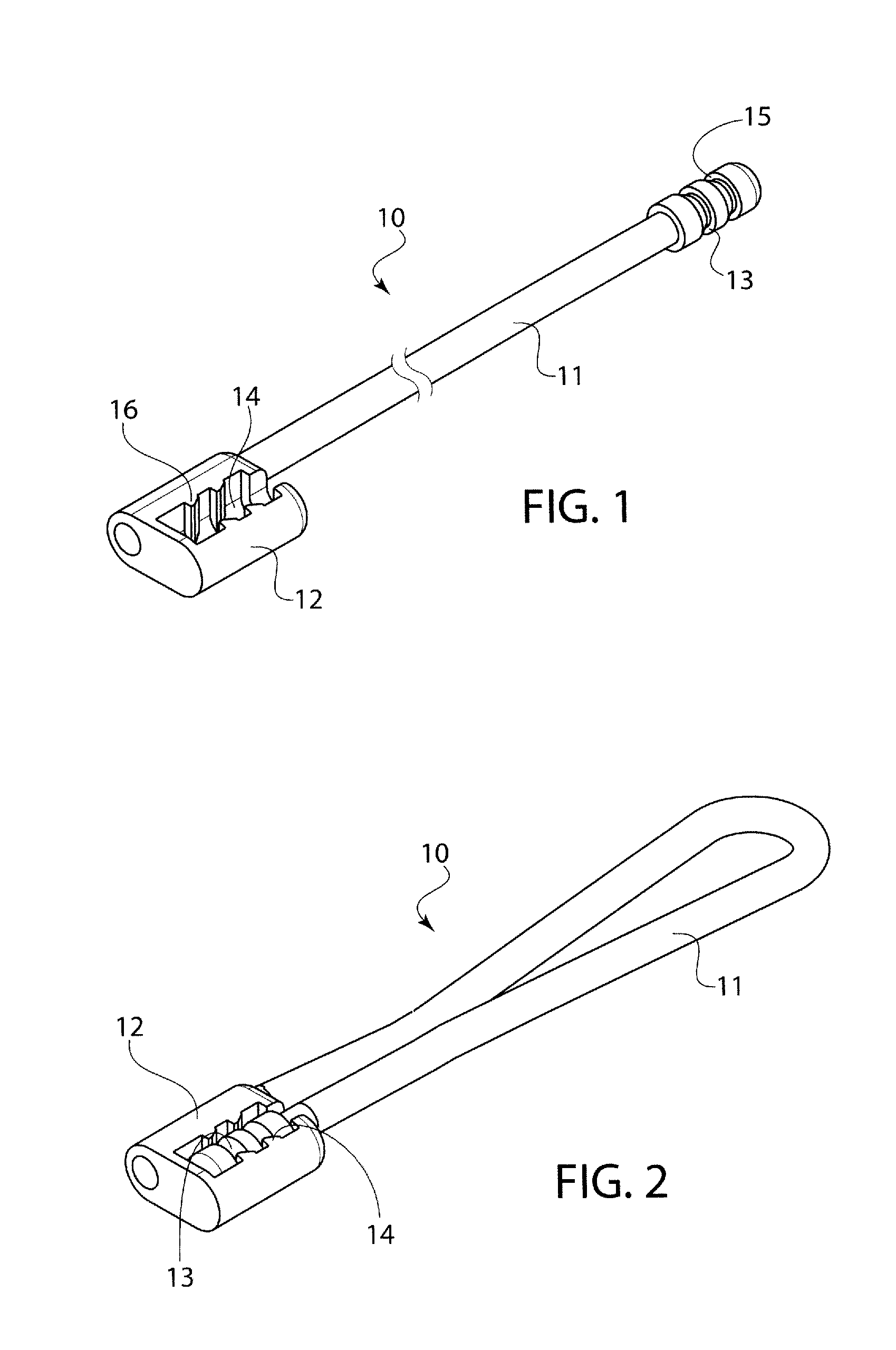
[0030]Referring now in detail to the drawings and, in particular, FIGS. 1 and 2 show a first embodiment of a pull tab 10 according to the invention. Pull tab 10 is comprised of a cord 11 having a cord retaining member 12 at one end and a plug 13 at the other end. Cord retaining member 12 and plug 13 are both over molded onto cord 11, which can be a woven cord made of any suitable material. Cord retaining member 12 has a socket 14 molded therein, for receiving plug 13 when cord 11 is folded over itself, as shown in FIG. 2. In order to ensure a secure fit of the plug 13 into socket 14, plug 13 has a series of grooves 15 encircling it, and socket 14 has a series of corresponding protrusions 16 that fit into the groove 15 when plug 13 is placed in socket 14.

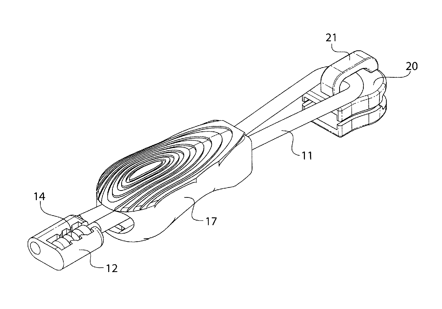
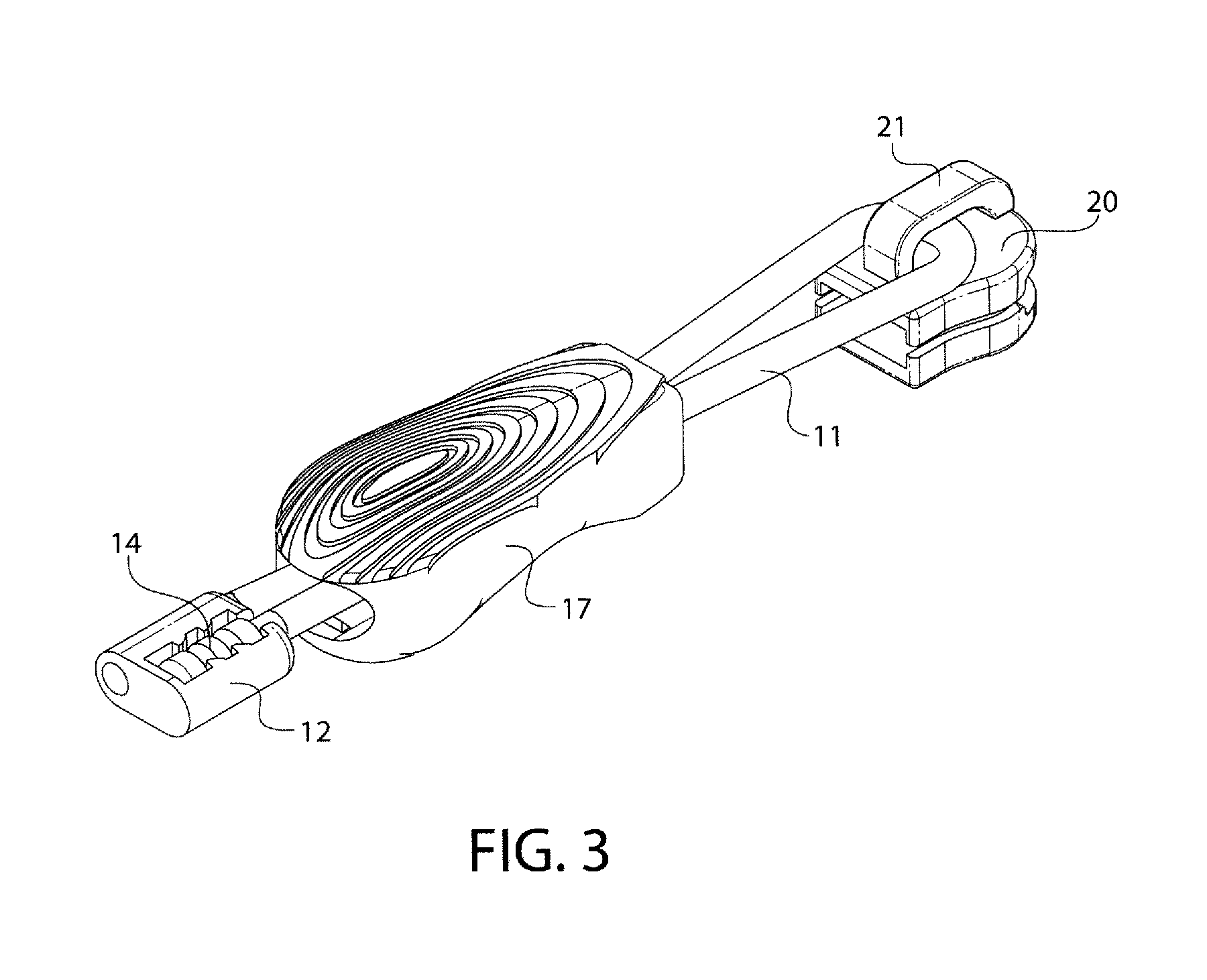
[0031]To attach pull tab 10 to a zipper head 20, plug 13 is first threaded through a slidable locking cover 17 and then through the bar 21, back through slidable locking cover 17, and finally placed in socket 13, as shown in FIG. 3. ...


PUM


Abstract

A pull tab for zippers is formed by a cord having a cord retaining member attached to one end of the cord and a socket in the top surface of the cord retaining member, and a plug attached to other end of the cord. The plug has a shape corresponding to the shape of the socket, so that the plug can fit securely within the socket, thus, forming a loop with the cord. A slidable locking device is placed around the cord, the locking device having an interior cavity corresponding to the shape of the cord retaining member, such that placing the plug into the socket and sliding the locking device over the cord retaining member locks the second end of the cord to the cord retaining member. In a method for manufacturing the pull tab, the plug and cord retaining member are continuously overmolded in one piece on a length of the cord, and then cut into pieces to form completed pull tabs.

Description

BACKGROUND OF THE INVENTION[0001]1. Field of the Invention[0002]The present invention relates to a pull tab for zippers, as well as a method for manufacturing a pull tab. In particular the invention relates to a pull tab that can be applied directly to the zipper head, and to a manufacturing method for continuously overmolding a cord to form the pull tab.[0003]2. The Prior Art[0004]Pull tabs for zippers are usually formed by metal plates having an aperture in which the zipper head is mounted. These metal plates are often too small to allow for easy sliding of the zipper. This is especially true when the zipper pull becomes wet and slippery. Therefore, many manufacturers attach a cord having a larger pull on the end to the existing zipper pull. However, these additional cords are often too long to make pulling easy, and the manufacturing process is expensive and time consuming.SUMMARY OF THE INVENTION[0005]It is therefore an object of the invention to provide a zipper pull that can b...

Claims


Application Information

Patent Timeline
Patent Type & Authority Patents(United States)
IPC IPC(8): A44B19/26A44B19/42F16G11/00
CPCA44B19/262A44B19/42F16G11/00
Inventor CHEN, TE CHIEN
Owner DURAFLEX HONG KONG
Why Eureka
Try Eureka