
Charging plug with locking identification

a charging plug and locking technology, applied in the direction of charging stations, electric vehicle charging technology, transportation and packaging, etc., can solve the problems of preventing the movement of the bolt, and unable to lock the plug. to be used, so as to achieve the effect of reliable protection against unauthorized access

Active Publication Date: 2016-11-22
KIEKERT AG
View PDF8 Cites 0 Cited by
  • Summary
  • Abstract
  • Description
  • Claims
  • Application Information

AI Technical Summary

Benefits of technology

The present invention provides a charging device for electric vehicles that can prevent unauthorized access. The device includes a lever that blocks the bolt in its starting position, preventing it from moving to its locking position. The lever only unlocks when it reaches its end position. This mechanical solution reduces the energy required for a connection between two charging devices, minimizing energy waste. The lever has an elongated hole that blocks the bolt in its starting position and allows it to lock when the lever reaches its end position. The bolt can be moved to its non-locking position after charging to disconnect the charging devices. This makes it convenient to operate the charging device with an electric drive system.

Problems solved by technology

Such a retaining opening may be damaged, for example, by a bar (hereinafter referred to as “locking bar”), that serves for the locking and has been broken off, to such an extent that a locking is no longer possible.
As a consequence, a lock damaged in the aforementioned manner will definitely not go unnoticed.
Instead, it is desirable that at least such damage to the retaining opening that renders a locking of a mechanical connection between two charging devices no longer possible would result in preventing the movement of the bolt in the direction of the locking position.

Method used


Image

  • Charging plug with locking identification
  • Charging plug with locking identification
  • Charging plug with locking identification

Examples


Embodiment Construction

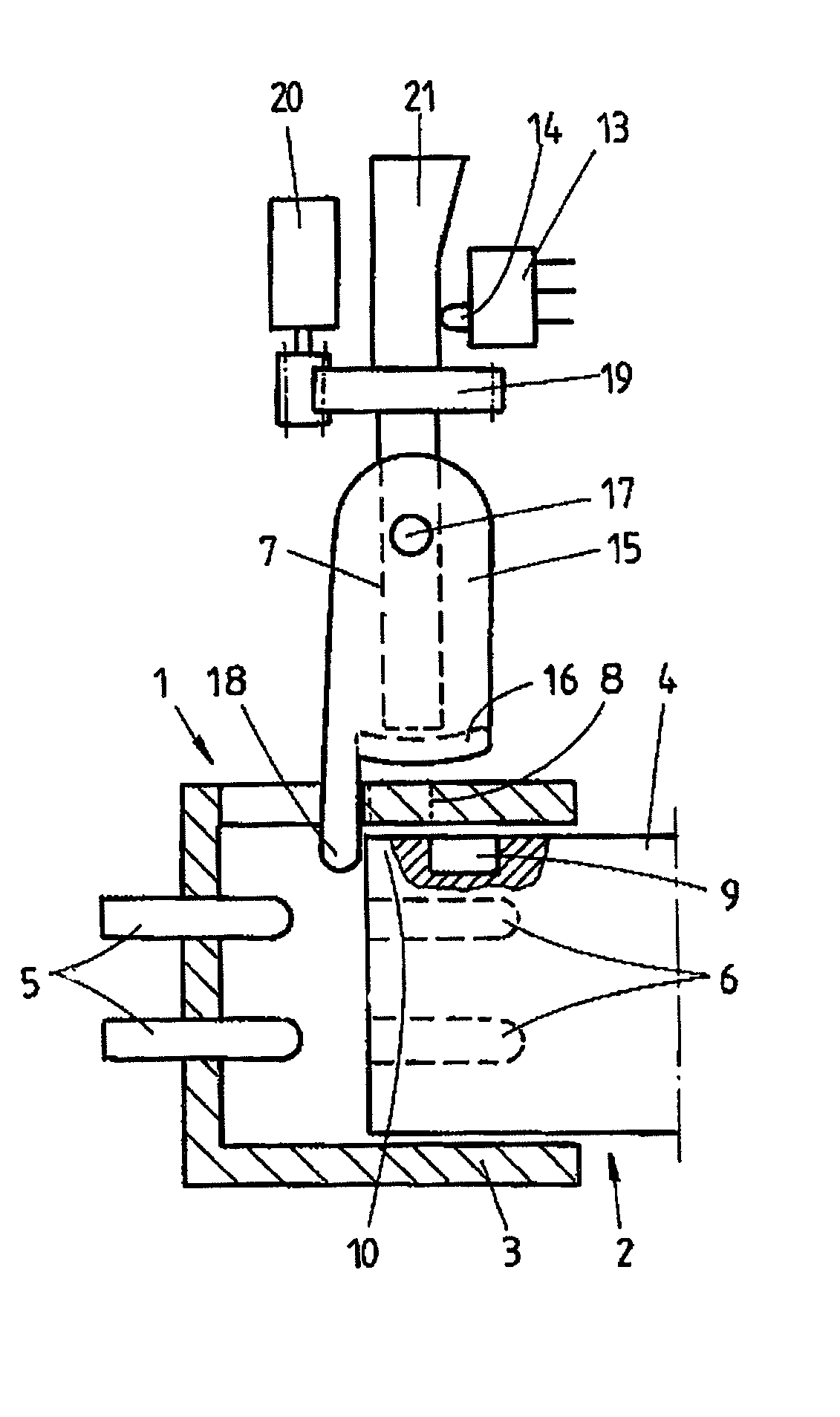
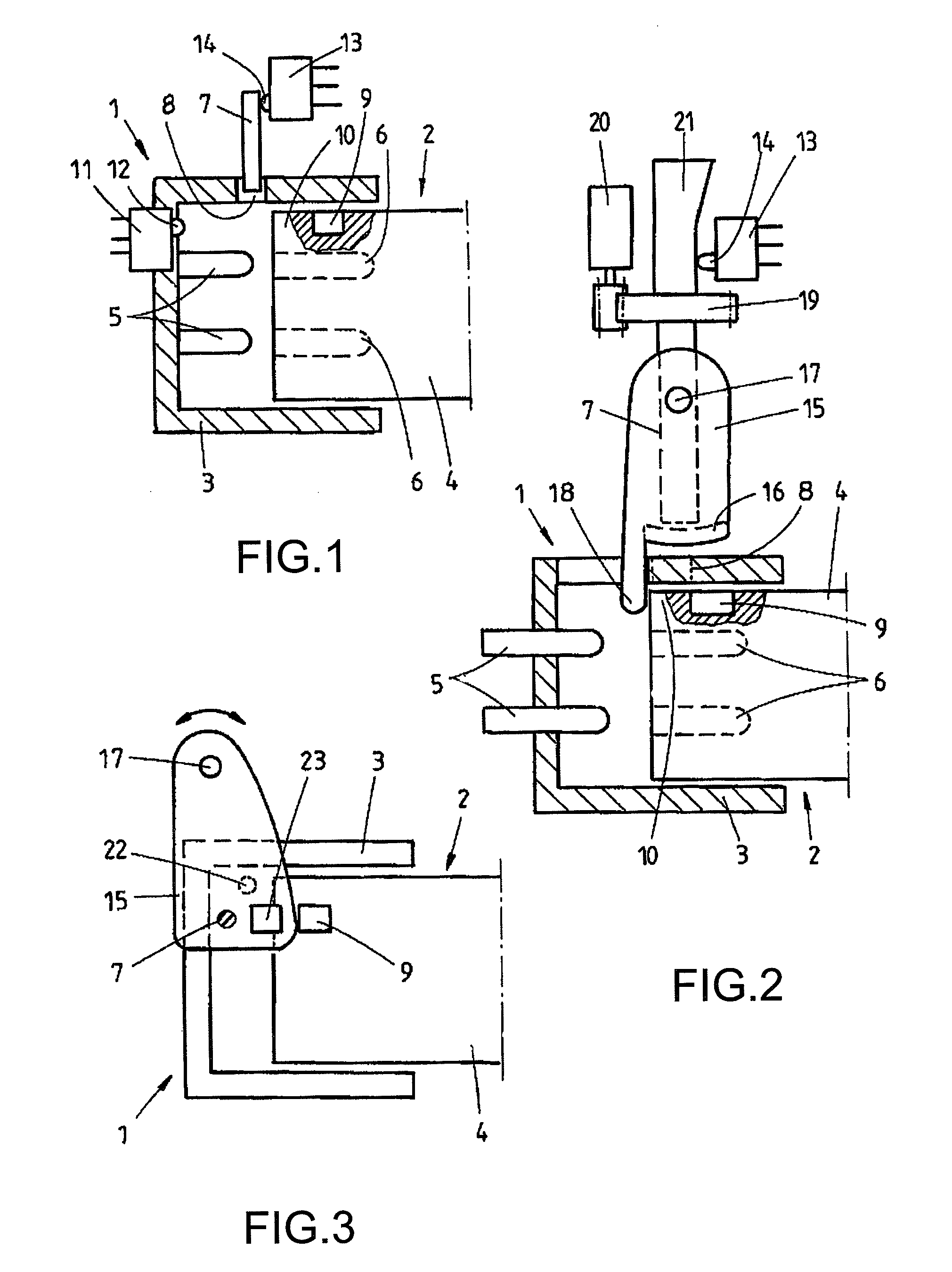
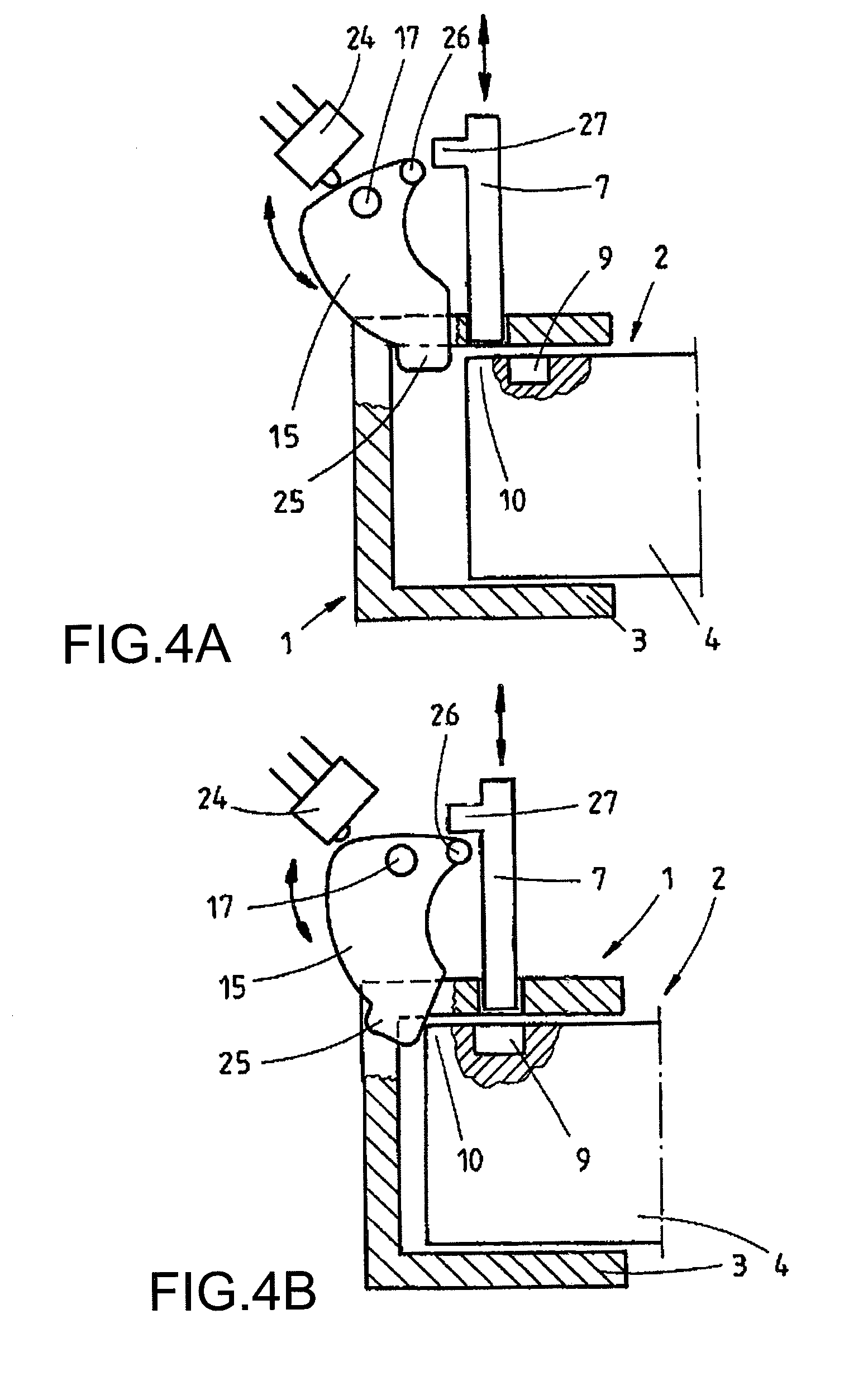
[0027]FIG. 1 shows a charging device 1 of an electric vehicle that is to be connected with a further loading device 2 of a loading station. The charging device 1 comprises a housing 3 into which the housing 4 of the loading device 2 can be inserted. At the base of the housing 3, the charging device 1 comprises a number of electrical contact pins 5 which serve for the charging with DC and / or AC voltage. The electrical contact pins 5 are either connected permanently with the housing 3 or can, for example, be moved by an electric drive system along their longitudinal axis for the establishment of an electrical connection. The loading device 2 comprises corresponding electrical contact sockets 6, into which the electrical contact pins 5 are moved during a mechanical connection or following the locking of such a mechanical connection into such a lock, in order to thereby produce an electrical connection between the two charging devices 1 and 2. The charging device 1 comprises a bolt 7 th...


PUM


Abstract

A charging device for an electric vehicle, which charging device can be protected against unauthorized access in a particularly reliable manner. The charging device for an electric vehicle has a bolt for locking a connection between the charging device and a further charging device. If the charging device is mechanically connected to a further charging device for charging purposes, this mechanical connection is then locked by a corresponding end of the bolt being moved into a retaining opening in the further charging device. A retaining opening of this kind can, for example, be damaged by a broken web which serves for locking such that locking is no longer possible. Therefore, a device is provided which can prevent movement of the bolt in the direction of a locking position when the retaining opening is damaged in this way. A locking arrangement which is damaged in the above manner therefore fundamentally does not remain unnoticed. Charging therefore preferably requires sufficiently undamaged, correct locking of the two charging devices involved.

Description

RELATED APPLICATION DATA[0001]This application is a continuation of U.S. application Ser. No. 14 / 004,207 filed Sep. 10, 2013 which is a National Phase of PCT / DE2011 / 001952 filed Nov. 8, 2011 which claims priority of German Application No. 10 2010 044 138.4 filed Nov. 18, 2010, all of which are hereby incorporated herein by reference in their entireties.FIELD OF THE INVENTION[0002]The invention relates to a charging device of an electric vehicle with the features of the preamble of claim 1.BACKGROUND[0003]An electric vehicle is a vehicle which is propelled by an electric motor. The electric motor draws its power from a battery which is housed in the electric vehicle. This battery needs to be charged again after a discharge. For charging the battery, a charging device is used in the sense of the present invention. The charging device can be a part of the electric vehicle or a part of a charging station. If the battery of an electric vehicle is to be charged, the charging device of a c...

Claims


Application Information

Patent Timeline
Patent Type & Authority Patents(United States)
IPC IPC(8): H02J7/00B60L11/18B60L1/00
CPCB60L11/1818B60L1/003B60L11/1824B60L11/1846B60L2270/32B60L2270/34Y02T10/7005Y02T10/7072Y02T90/121Y02T90/128Y02T90/14Y02T90/163Y02T90/169Y04S30/14B60L53/16B60L53/30B60L53/65Y02T10/70Y02T90/12Y02T90/167Y02T90/16
Inventor KORDOWSKI, BERNHARDSCHOLZ, MICHAELWESTERWICK, VOLKER
Owner KIEKERT AG
Learn More