Unlock instant, AI-driven research and patent intelligence for your innovation.
Conveying system, and use of a chamber extending inwardly with respect to a plastic module in a conveying system
Inactive Publication Date: 2016-11-22
REXNORD FLATTOP EURO BV
View PDF14 Cites 7 Cited by
Summary
Abstract
Description
Claims
Application Information
AI Technical Summary
This helps you quickly interpret patents by identifying the three key elements:
Problems solved by technology
Method used
Benefits of technology
Benefits of technology
The patent describes a plastic module used in a conveying system. The module has a chamber that makes contact with a return guide during circulation. By forming the chamber with two line contacts, the module is properly guided and can make stable travel around the return guide. The shape of the chamber can be different, as long as it makes contact with the return guide at two lines. This design makes it easy to replace the module when the conveyor mat needs to be replaced, without requiring different plastic modules or mats. The spacing between the two line contacts ensures a stable circulation of the module around the return guide.
Problems solved by technology
A drawback of the known systems is that when the modules of the mat are worn, the mat has to be replaced by a mat with modules having chambers with concave, circular cylindrical surfaces that correspond to the radii of a guide surface of the return guides.
This has as a drawback, for example, that at suppliers, this may lead to large stocks consisting of many different modules and mats.
Further, this may for instance lead to longer delivery times in that a supplier does not have the proper modules and / or mats in stock, and / or in that the logistics have thereby become complex.
This is not desirable because it may, for instance, cause a production line, of which the conveying system forms a part, to remain out of use for a long period of time.
It is also a drawback that a manufacturer of plastic modules, for the production of different modules with chambers of different dimensions, has to invest in different production means, such as different injection molding molds for the different modules with chambers of different dimensions.
This can also lead to large stocks at the manufacturer's and / or in the distributive trade and, for instance, the delivery times from the manufacturer to one of his buyers can become longer.
Method used
Image
Click on the blue label to locate the original text in one second.
Reading with bidirectional positioning of images and text.
Examples
first embodiment
[0037]FIG. 3 shows a schematic perspective view of a plastic module 6 of a conveying system according to the invention. The module 6 can comprise, for instance, one or more cavities 16 in which drive means can engage for advancing the conveyor mat 3 in conveying direction T. It is noted that the module 6 can also be driven in an alternative manner, as, for instance, with the aid of a gear transmission or by means of a contactless drive, for instance, with the aid of magnets.
[0038]FIGS. 4a-4d show different embodiments of chambers 11 of a plastic module 6 of a conveying system according to the invention. In the embodiments shown, the chamber 11, viewed in conveying direction T, is located substantially centrally between the hinge loops 7 provided at the front and rear side of the module 6. Alternatively, the chamber 11, viewed in conveying direction T, can be placed further forward or, conversely, further rearwards.
second embodiment
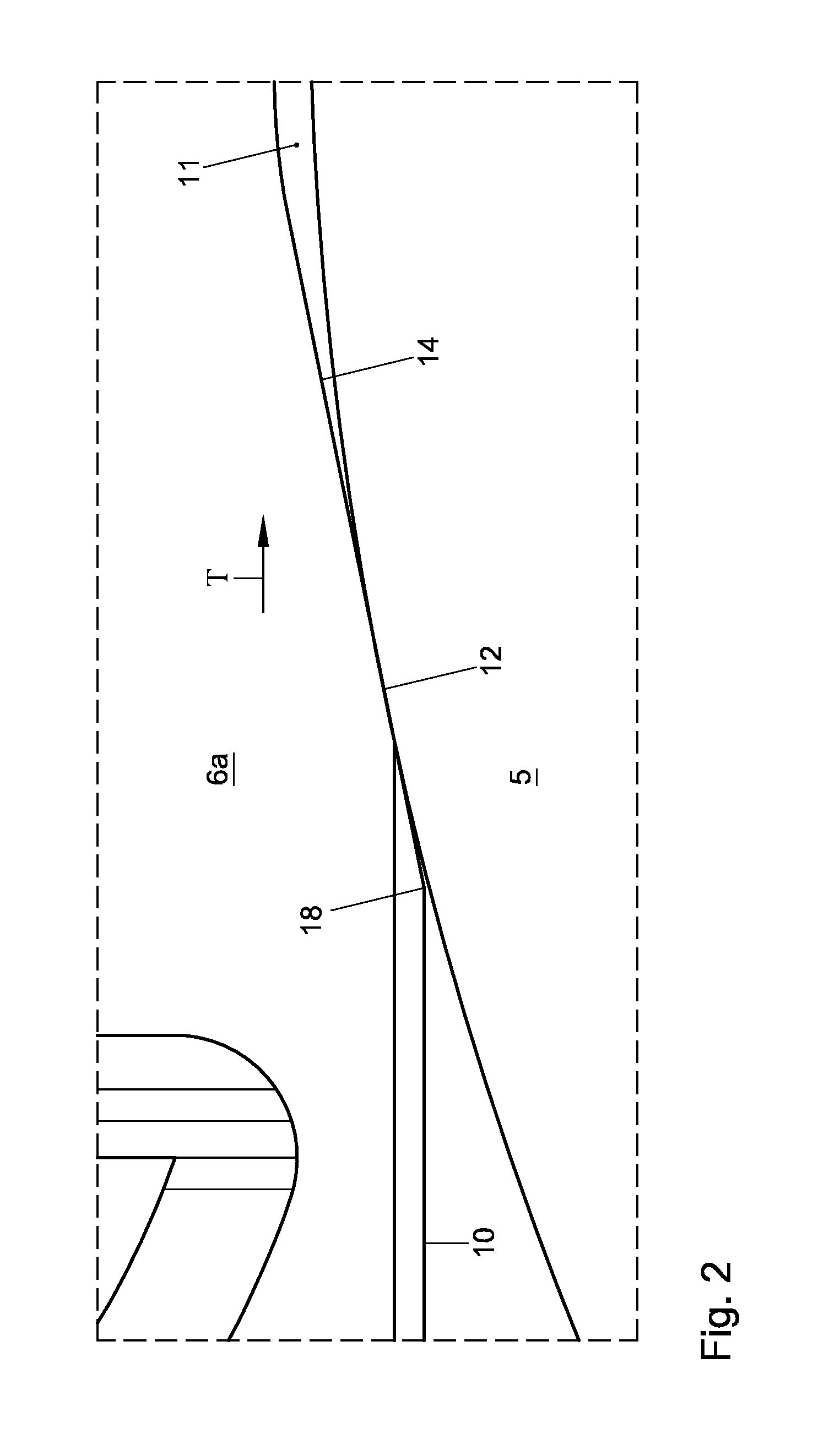
[0039]FIG. 4a shows a schematic view of a plastic module 6 of a conveying system according to the invention. The first surface part 14 and the second surface part 15 converge substantially in a direction B inward with respect to the circulating module 6.
[0040]The first surface part 14 can be a first substantially flat surface part 14′ and the second surface part 15 can be a second substantially flat surface part 15′, with the two flat surface parts 14′, 15′ being at a mutual angle a. The angle a is between 0′ and 90′.
[0041]Further, the first surface part 14 and the second surface part 15 can link up with each other in a roof-shaped manner. As the first and the second surface part in FIG. 4a link up with each other at an angle a, a roof-shaped, triangular prismatic chamber 11 is obtained.
third embodiment
[0042]FIG. 4b shows a schematic view of a plastic module 6 of a conveying system according to the invention. The first surface part 14 is a first convex surface part 14″ and the second surface part 15 is a second convex surface part 15″. The first surface part 14″ and the second surface part 15″ are connected by one intermediate concave surface part 16″. Alternatively, the intermediate surface part 16 can also be a flat surface part 16 or a convex surface part 16.
[0043]It is noted that the first surface part 14 and the second surface part 15 may alternatively be connected to each other by several intermediate surface parts 16. Each intermediate surface part 16 can be a flat surface part 16′, as shown in FIG. 4c, a concave surface part 16″, as shown in FIG. 4b, or a convex surface part 16′″.
PUM
Abstract
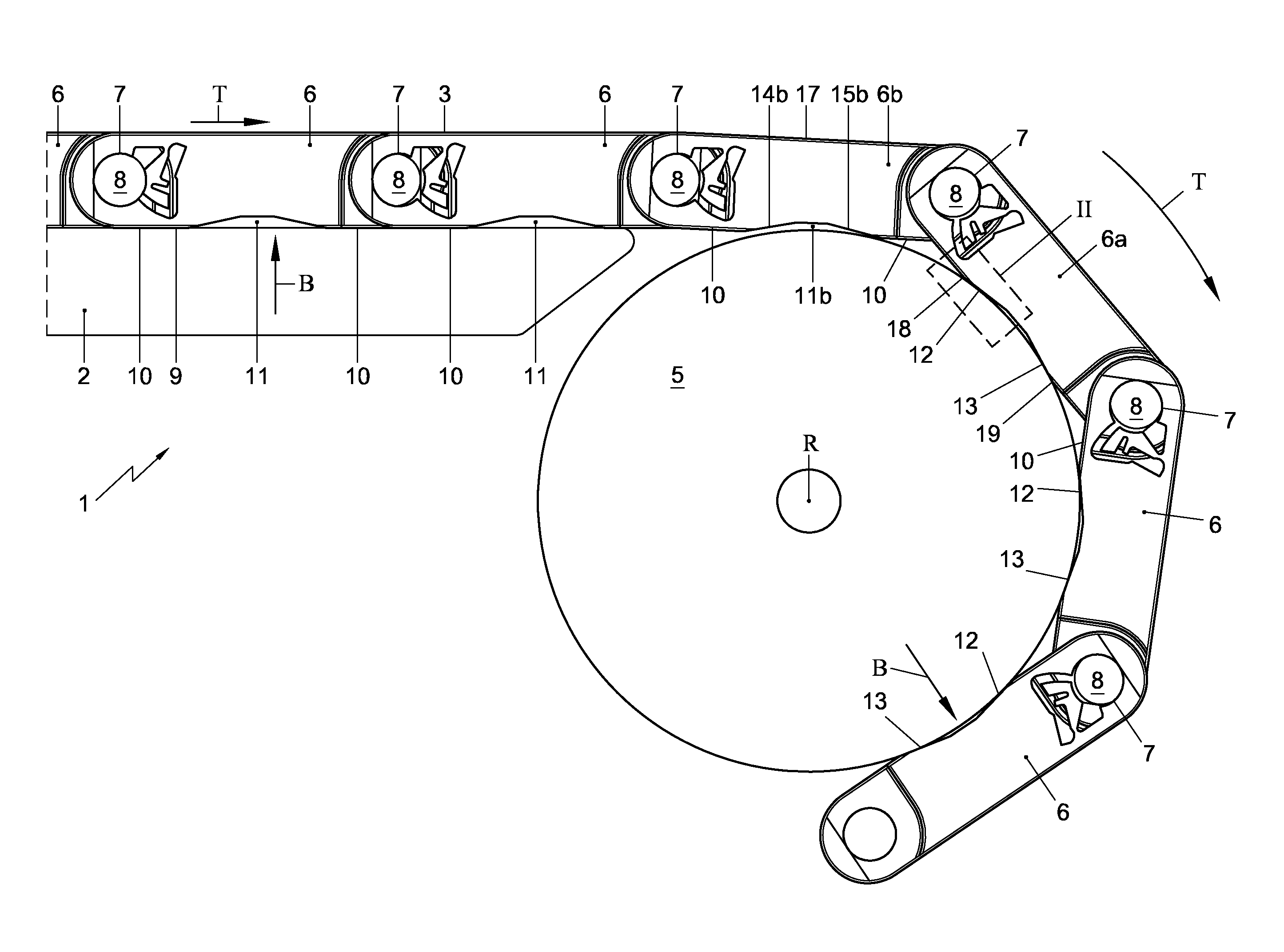
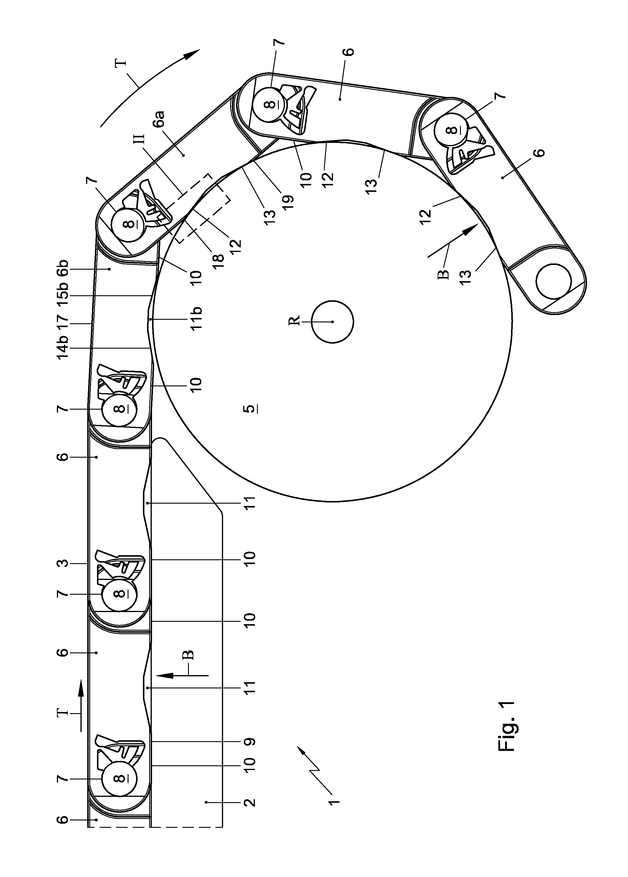
The invention relates to a conveying system. The conveying system comprises a conveying track, an endless conveyor mat for conveying products in a conveying direction, a drive for driving the conveyor mat, and a return guide provided at the conveying track for guiding the conveyor mat upon circulation. The return guide extends substantially transversely to the conveying direction. The conveyor mat comprises a number of plastic modules, which are provided at their bottom side with a track guide surface, while at least a part of the plastic modules at the location of the respective track guide surface comprise at least one chamber extending inwardly with respect to the module for being in a contact with the return guide during circulation of the module around the return guide. The chamber is formed such that the contact upon circulation consists of a first line contact and a second line contact.
Description
CROSS-REFERENCE TO RELATED APPLICATIONS[0001]This application represents the national stage entry of PCT International Application No. PCT / NL2012 / 050163 filed on Mar. 16, 2012 and claims the benefit of Netherlands patent application no. 2006418 filed Mar. 18, 2011. The content of each of these applications is hereby incorporated by reference as if set forth in its entirety herein.STATEMENT REGARDING FEDERALLY SPONSORED RESEARCH OR DEVELOPMENT[0002]Not applicable.FIELD OF THE INVENTION[0003]The invention relates to a conveying system, comprising a conveying track, an endless conveyor mat designed to circulate around the conveying track and suitable for conveying products in a conveying direction, a drive for driving the conveyor mat, and a non-driving return guide provided at the conveying track for guiding the conveyor mat upon circulation, which return guide extends substantially transversely to the conveying direction, wherein the conveyor mat comprises a number of plastic modules...
Claims
Application Information
Patent Timeline
Application Date:The date an application was filed.
Publication Date:The date a patent or application was officially published.
First Publication Date:The earliest publication date of a patent with the same application number.
Issue Date:Publication date of the patent grant document.
PCT Entry Date:The Entry date of PCT National Phase.
Estimated Expiry Date:The statutory expiry date of a patent right according to the Patent Law, and it is the longest term of protection that the patent right can achieve without the termination of the patent right due to other reasons(Term extension factor has been taken into account ).
Invalid Date:Actual expiry date is based on effective date or publication date of legal transaction data of invalid patent.
IPC IPC(8): B65G47/00B65G17/08B65G17/40
CPCB65G17/08B65G17/40B65G2207/12
Inventor CORNELISSEN, LEONARDUS ADRIANUS CATHARINUSSIGMOND, RONALD

