Glow discharge ion source

a technology of ion source and ion source, which is applied in the field of ion source and mass spectrometer, can solve the problems of electron capture dissociation technique, prohibitively expensive mass spectrometer for the majority of mass spectrometry users, and difficulty in knowing a priori the optimal parameters

Active Publication Date: 2016-11-22
MICROMASS UK LTD
View PDF21 Cites 2 Cited by
  • Summary
  • Abstract
  • Description
  • Claims
  • Application Information

AI Technical Summary

Problems solved by technology

However, the technique of Electron Capture Dissociation suffers from the significant problem that it is necessary simultaneously to confine both positive ions and electrons at near thermal kinetic energies.
However, such mass spectrometers are very large and are prohibitively expensive for the majority of mass spectrometry users.
It can be difficult to know a priori the optimal parameters for every anion-cation combination from an LC run.
A problem with known mass spectrometers which incorporate an Electron Transfer Dissociation fragmentation cell is that the reagent anions which are used to cause analyte cations to fragment are generated by an additional ion source (e.g. an Atmospheric Pressure Chemical Ionisation ion source) which is arranged alongside an ion source (e.g. an Electrospray ion source) which is used to ionise the sample of interest.
Locating two ion sources in close proximity to the inlet to the mass spectrometer is problematic.
Furthermore, the known arrangement can suffer from the problem of cross-talk.
A yet further problem with the known arrangement is that the reagents which are produced from the Atmospheric Pressure Chemical Ionisation ion source may be carcinogenic.
Another problem with the known arrangement is that the sensitivity of the Atmospheric Pressure Chemical Ionisation ion source for generating the reagent ions is relatively low.

Method used


Image

  • Glow discharge ion source
  • Glow discharge ion source
  • Glow discharge ion source

Examples


Embodiment Construction

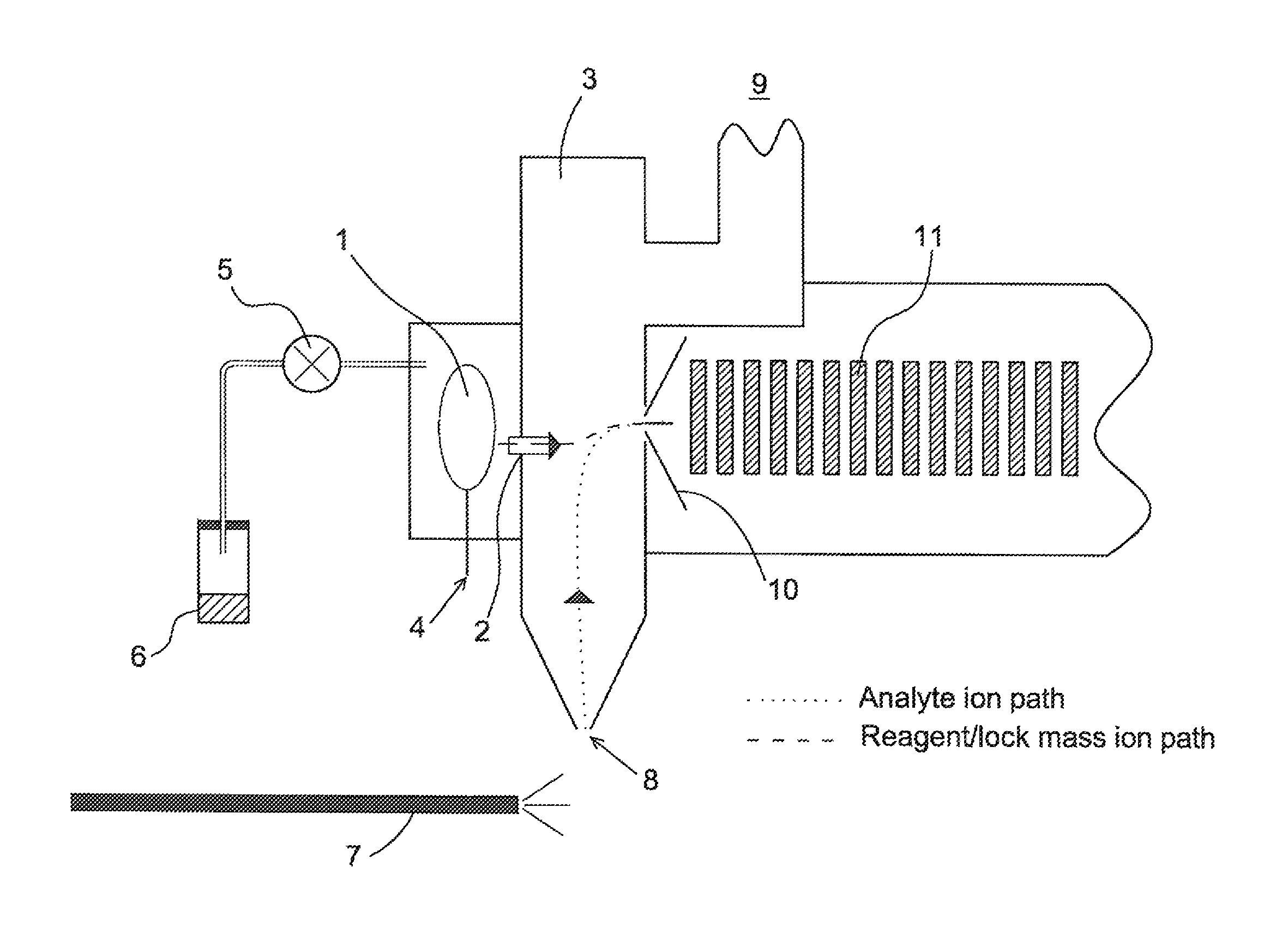
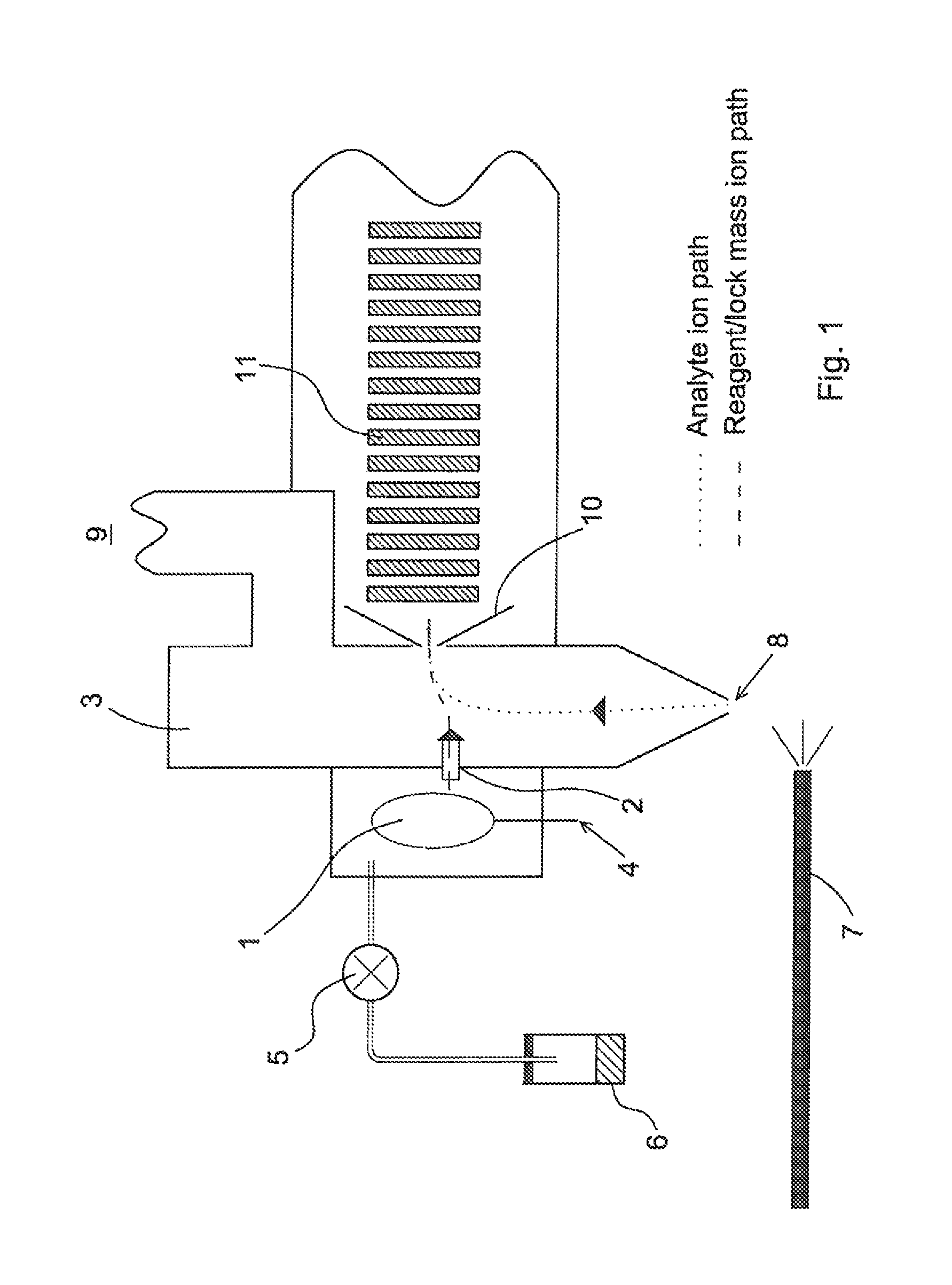
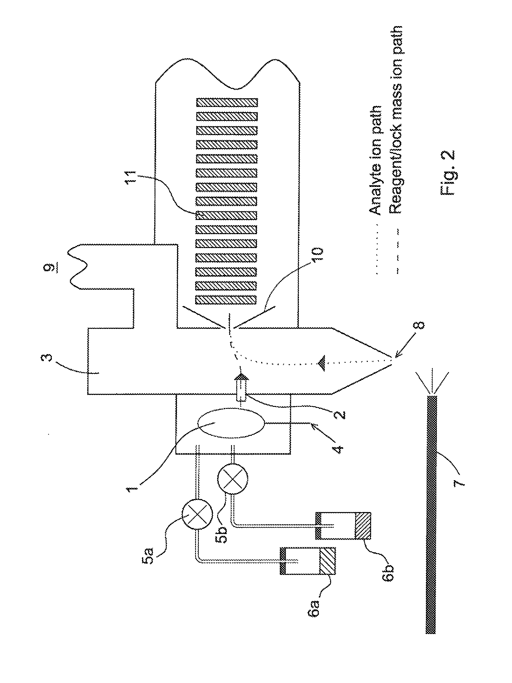
[0185]An embodiment of the present invention will now be described with reference to FIG. 1 which shows an atmospheric pressure Electrospray ionisation ion source 7 arranged adjacent to the inlet and sample cone 8 of a mass spectrometer. A glow discharge source comprising an electrode or pin 4 is preferably provided in a housing adjacent to a first vacuum chamber 3 of the mass spectrometer. The electrode or pin 4 is preferably connected to an external high voltage supply. The housing is preferably maintained at a relatively high or intermediate pressure and the application of a relatively high voltage to the electrode or pin 4 preferably causes a glow discharge 1 to occur within the housing.

[0186]A volatile reagent 6 is preferably fed into the housing and is preferably injected into the glow discharge volume 1 which is preferably formed within the housing. The flow of reagent 6 is preferably controlled by a valve or micro-dosing device 5. When a high voltage is applied to the discha...


PUM

PropertyMeasurementUnit
pressureaaaaaaaaaa
voltageaaaaaaaaaa
pressuresaaaaaaaaaa

Abstract

A mass spectrometer is disclosed comprising a glow discharge device within the initial vacuum chamber of the mass spectrometer. The glow discharge device may comprise a tubular electrode located within an isolation valve, which is provided in the vacuum chamber. Reagent vapor may be provided through the tubular electrode, which is then subsequently ionized by the glow discharge. The resulting reagent ions may be used for Electron Transfer Dissociation of analyte ions generated by an atmospheric pressure ion source. Other embodiments are contemplated wherein the ions generated by the glow discharge device may be used to reduce the charge state of analyte ions by Proton Transfer Reaction or may act as lock mass or reference ions.

Description

CROSS REFERENCE TO RELATED APPLICATIONS[0001]This application is a continuation of U.S. patent application Ser. No. 13 / 055,612, filed on Apr. 5, 2011, pending, which is the National Stage of International Application No. PCT / GB09 / 001842, filed on Jul. 27, 2009 and designating the United States, which claims benefit of and priority to Provisional Patent Application No. 61 / 086,213, filed Aug. 5, 2008, and United Kingdom Patent Application No. 0813777.0, filed Jul. 28, 2008. These applications are incorporated herein by reference in their entirety.BACKGROUND OF THE INVENTION[0002]The present invention relates to an ion source, a mass spectrometer, a method of generating ions and a method of mass spectrometry.[0003]Electrospray ionisation ion sources are well known and may be used to convert neutral peptides eluting from an HPLC column into gas-phase analyte ions. In an aqueous acidic solution, tryptic peptides will be ionised on both the amino terminus and the side chain of the C-termi...

Claims


Application Information

Patent Timeline
Patent Type & Authority Patents(United States)
IPC IPC(8): G01N24/00H01J49/12H01J49/04H01J49/16H01J49/10H01J49/00
CPCG01N24/00H01J49/0009H01J49/0072H01J49/0495H01J49/107H01J49/12H01J49/165Y10T436/24H01J49/062H01J49/10H01J49/168
Inventor BROWN, JEFFERY MARKGREEN, MARTIN RAYMONDPRINGLE, STEVEN DEREK
Owner MICROMASS UK LTD
Why Eureka
Try Eureka