Apparatus and methods for holographic display

a technology of electroholographic display and apparatus, which is applied in the field of electroholographic display, can solve the problems of not being able to reach acceptable performance levels, the space-bandwidth product of commercially available pixelated slms is quite small compared to conventional light-sensitive materials used for holographic recording, and the approach is not suitable for curved display devices

Active Publication Date: 2016-11-22
ONURAL LEVENT
View PDF7 Cites 54 Cited by
  • Summary
  • Abstract
  • Description
  • Claims
  • Application Information

AI Technical Summary

Benefits of technology

[0015]The object of the invention is to provide an apparatus and methods for an axially symmetric electro-holographic display through use of an axially symmetric mirror, wherein the axially symmetric mirror reflects incident light axially symmetrically onto multiple planar SLMs forming a curved configuration and wherein the device permits free user movement without degradation in perception of the viewed image.
[0016]A further object of the invention is to provide an apparatus and methods for an improved axially symmetric electro-holographic display that includes relay lens modules to render the SLM plane virtually continuous and for providing a continuous viewing zone to the user.
[0021]An axially symmetric configuration for a curved holographic display can be achieved with multiple planar SLMs and an axially symmetric mirror. The diffracted light beams from each SLM over a segmented axially symmetric configuration of SLMs may be superposed above the axially symmetric mirror, through the use, for example, of a relay optical system. In this way, a display that has an Omni directional and continuous holographic viewing zone is feasible. Thus, the holographic display can provide the user with an Omni directional and continuous viewing zone that permits freedom of user movement along the horizontal plane.

Problems solved by technology

Nevertheless, such SLMs are not yet capable of reaching acceptable performance levels.
For example, the space-bandwidth product of commercially available pixelated SLMs is quite small compared to conventional light-sensitive materials used for holographic recording.
However, such an approach is suitable only for planar configurations due to the geometry of the replication optics; in particular, this approach is not suitable for curved display devices.
However, such an approach may not be suitable for commercial applications, because the design of the light illumination optics for multiple SLMs is very complex, and because a cylindrical configuration that has a 360 degree continuous viewing zone cannot be implemented.
Furthermore, this technique is not suitable for full parallax holographic display, because of the reduced vertical resolution on the SLM plane.
On the contrary to this, one of the disadvantages of this hologram is that it can display only still three-dimensional image due to the recording of holographic elements on a photo-refractive material.
Even though such approach can provide the three-dimensional representation holographically, it may not be proper for a moving object display for example a holographic-TV and holographic video.
In other words, the presented system may not be suitable to display a three-dimensional object in a space and its viewing angle is also restricted by the projection system.

Method used


Image

  • Apparatus and methods for holographic display
  • Apparatus and methods for holographic display
  • Apparatus and methods for holographic display

Examples


Embodiment Construction

[0023]An apparatus and methods for holographic display realized in order to fulfill the objects of the present invention is illustrated in the attached figures, where:

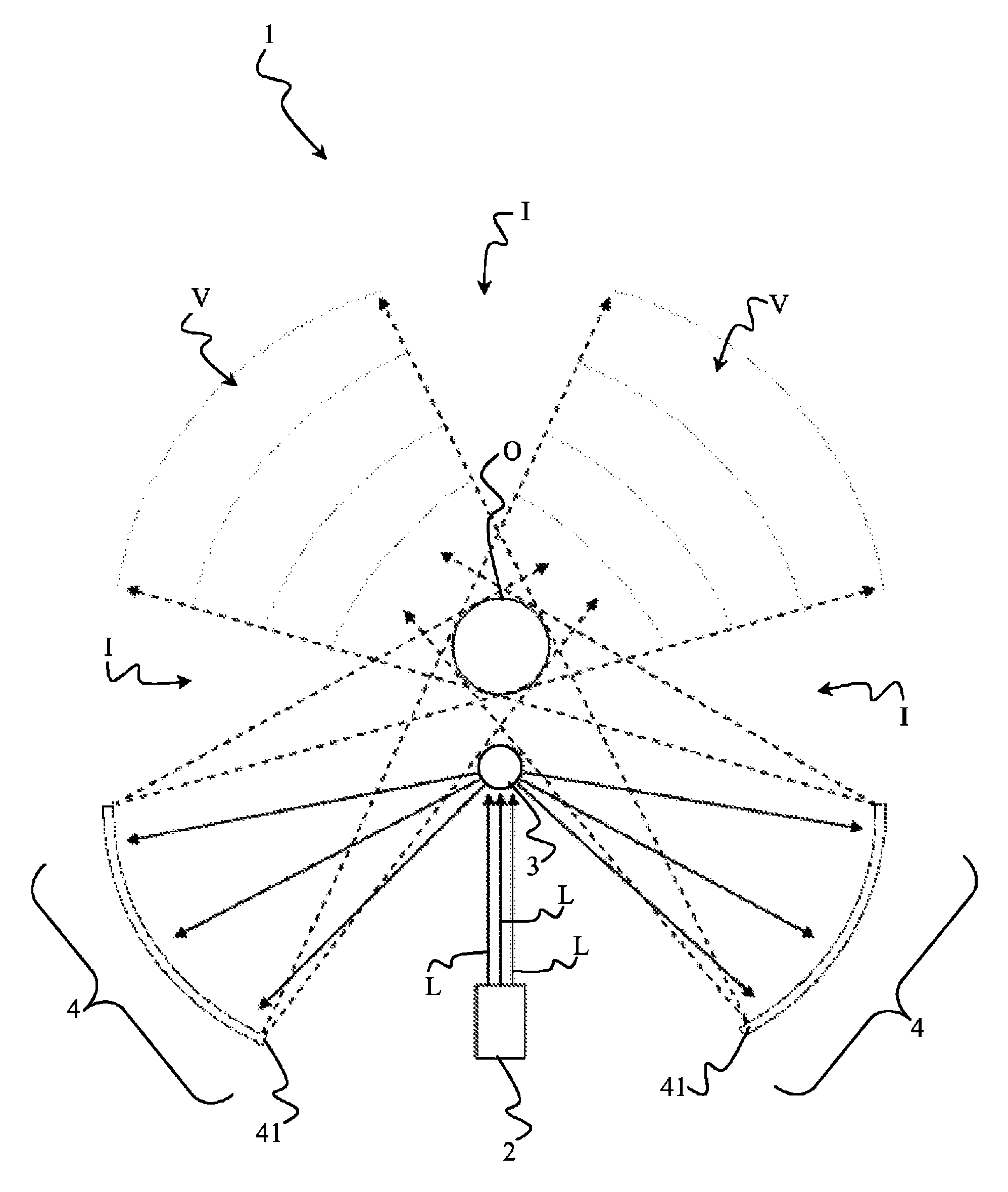
[0024]FIG. 1 shows a cross-sectional view of an axially symmetric holographic display in accordance with an embodiment of the invention.

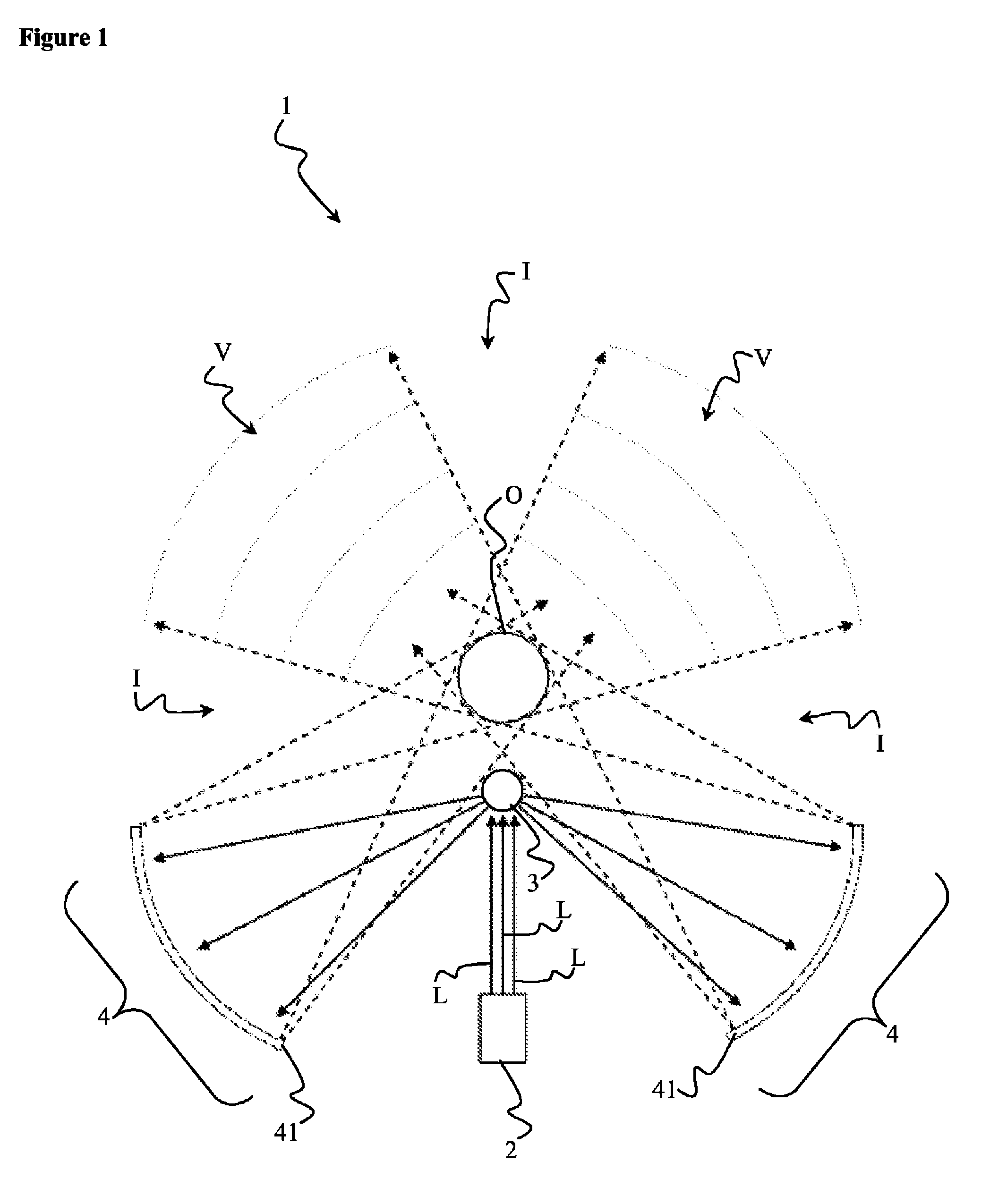
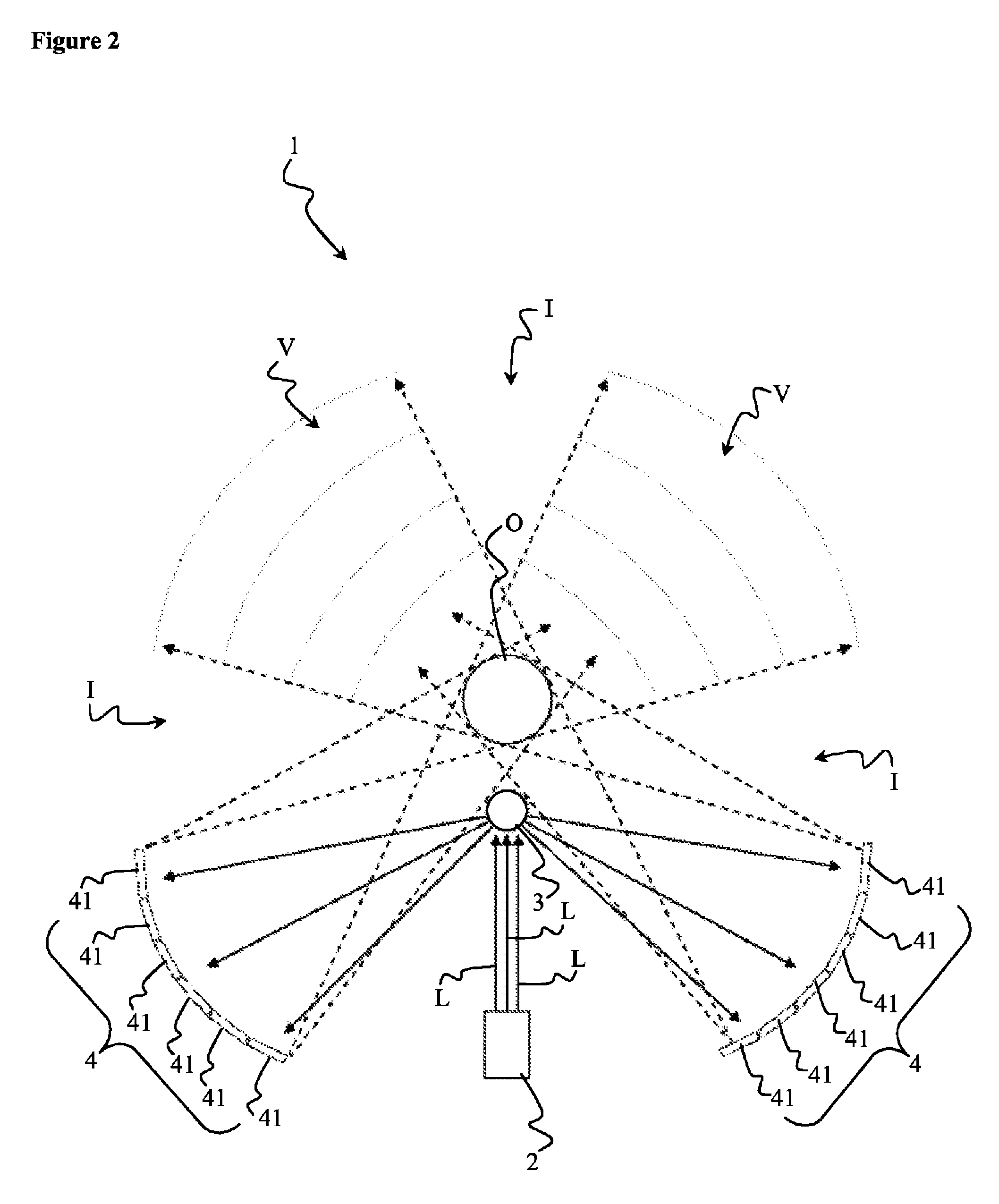
[0025]FIG. 2 shows a cross-sectional view of an axially symmetric holographic display in accordance with an embodiment of the invention that includes a plurality of planar SLMs.

[0026]FIG. 3 shows a side view of a cylindrically configured embodiment in which a cylindrical holographic display comprises a light source, a collimator optical system, vertically tilted multiple SLMs that do not include protective mounts and a cone mirror.

[0027]FIG. 4 shows a top view of a cylindrically configured embodiment that provides a continuous viewing zone and that includes a cone mirror, an area for optical reconstruction, and a cylindrically configured SLM layer.

[0028]FIG. 5 shows a continuous, singl...


PUM


Abstract

A holographic display and more particularly an apparatus and method for a curved electro-holographic display are disclosed. The apparatus mainly includes at least one light source for providing lights, at least one axially symmetric mirror for reflecting the lights coming from the light source, at least one spatial light modulation system having one or more than one spatial light modulators for modulating the lights reflecting from the axially symmetric mirror and forming a desired optical reconstruction above the axially symmetric mirror by reflecting the lights which is seen from a viewing zone by the user.

Description

RELATED APPLICATION INFORMATION[0001]This application is a 371 of International Application PCT / IB2011 / 050180 filed 14 Jan. 2011 entitled “An Apparatus And Methods For Holographic Display”, which was published in the English language 19 Jul. 2012, with International Publication Number WO 2012 / 095703 A1, the contents of which are incorporated herein by reference.FIELD OF THE INVENTION[0002]The present invention relates to a holographic display and more particularly to an apparatus and methods for a curved electro-holographic display.BACKGROUND OF THE INVENTION[0003]Holographic displays are means of generating realistic reconstruction of a three-dimensional (“3-D”) object or scene, because they can provide the required depth cues corresponding to the 3-D object or scene exactly. Using holographic techniques, the wave front reflected from an object may be recorded by means of a light sensing device through light interference with a reference wave, or generated based on numerical comput...

Claims


Application Information

Patent Timeline
Patent Type & Authority Patents(United States)
IPC IPC(8): G03H1/08G02B5/32G03H1/04G03H1/22G03H1/26G03H1/02
CPCG03H1/2202G03H1/2294G03H1/26G03H1/2205G03H2001/0224G03H2001/2242G03H2223/24G03H2225/55G03H2225/60
Inventor KANG, HOONJONGYARAS, FAHRIONURAL, LEVENT
Owner ONURAL LEVENT
Why Eureka
Try Eureka