Apparatus and method of generating quiet zone by cancellation-through-injection techniques

a technology of cancellation and injection, applied in the direction of active noise control, instruments, sound producing devices, etc., can solve the problems of difficult or impossible reception of desired signals, difficult to avoid actual problems, undesired artifacts in signals, etc., and achieve the effect of reducing or eliminating interferen

Active Publication Date: 2016-11-22
SPATIAL DIGITAL SYST
View PDF21 Cites 9 Cited by
  • Summary
  • Abstract
  • Description
  • Claims
  • Application Information

AI Technical Summary

Benefits of technology

[0020]Accordingly, an embodiment of the present invention provides mitigation techniques for RF systems against strong interferences either due to self-jamming or from external RF sources enabling desired Rx apertures to function properly under strong jamming conditions. More specifically, the present invention relates to architectures and designs of antenna systems aimed to reduce or eliminate interference due to jamming, either self-induced or from an external source, comprising an RF antenna, a beam forming network, and an optimization processor. The present invention further comprises a series of injection arrays being fed a series of signals from the optimization processor and beam forming network.
[0021]An embodiment of the present invention disclosing functions of the injection arrays with a feed back loop are to minimize undesired self-jamming signals iteratively by dynamically updating the amplitudes and phases weightings, or equivalents, of individual elements in the injection array. The weightings of all elements are the components of a vector referred as a “cancellation weighting vector” or a CWV. The inputs to the injection arrays are from pickup ports, placed adjacent to transmit apertures. The feed back loop to the injection arrays features many diagnostic probes, which are distributed in the quiet zones and will be used to measure the strengths of combined interference signals. An optimization processor in the feed back loop converts the measurements from each probe into performance indexes. These are called cost functions and must be positively definite. The summation of all the cost functions is referred to as the total cost of the current performance measure for the injection arrays. The to-be-updated weights in the next iteration for individual elements of the injection arrays are calculated based on the gradient of the performance measurements by optimization algorithms minimizing the total cost iteratively.
[0024]An optimization processor in the feed back loop converts the measurements from each probe into performance indexes; which are called cost functions and must be positively definite. The summation of the all cost functions is referred as the total cost of the current performance measure for the injection arrays. The to-be-updated weights for the next iteration of individual elements in the injection arrays are calculated based on the gradient of the performance measurements by optimization algorithms minimizing the total cost iteratively.
[0025]At an optimized state after the iterative results converge; significantly reduced cost will be the result. Consequently, the external jamming signals are minimized over a quiet zone within which the sensitive Rx apertures reside. Therefore the Rx front-ends will be well protected from “saturations” by the strong external jammers.
[0026]A third embodiment of the present invention discloses functions of the injection arrays with a feed back loop for handheld personnel devices with multi-functions capability. For example, devices such as 4G cell phones are designed to minimize undesired self jamming signals iteratively by dynamically updating the amplitudes and phases weightings, or equivalents, of individual elements in the injection array. The leakage may be from a Bluetooth transmission to sensitive WiFi receivers operating in the same ISM (industrial, scientific, medical) frequency channels. The weightings of all elements in an injection array are the components of a vector referred as a “cancellation weighting vector” or a CWV. The inputs to the injection arrays are from a pick up antenna adjacent to Blue Tooth antennas which only pick up jamming BT signals. The feed back loop to the injection arrays features a few diagnostic probes over quiet zones for the WiFi Rx apertures and will be used to measure the strengths of combined interference signals. An optimization processor in the feed back loop converts the measurements from each of the probes into performance indexes; which are called cost functions and must be positively definite. The summation of the all cost functions is referred as the total cost of the current performance measure for the injection arrays. The to-be-updated weights in the next iteration for individual elements of the injection arrays are calculated based on the gradient of the performance measurements by an optimization algorithm minimizing the total cost iteratively. At an optimized state after the iterative results converge, the resulting cost will be reduced significantly. Consequently, the internal strong leakage signals are minimized over a quiet zone within which the sensitive WiFi Rx apertures are resided. Thus, the WiFi Rx front-ends will be well protected from “saturations” by the strong internal interferences.

Problems solved by technology

In fact, it is actually difficult to avoid.
By definition, interference originates from a source external to a signal path and produces undesired artifacts in the signal.
The purpose of intentional radio jamming is to make reception of desired signals difficult or impossible.
On the other hand, power jammers feature very strong signals to saturate front-ends (the transmitting side) of communications, radiometers, or radar receivers, producing high intermodulation (IM) noises over receiving bandwidths, thus blocking communications signals.
Nevertheless, performance will significantly degrade if any strong interference source coexists with the information signal.
In practice, the received GPS satellite signal is about −160 dBm on the ground, and is too weak to tolerate any existence of easily generated strong unintentional RF interference and intentional jammers.
However, a full duplex receiver is susceptible to a problem called “self-interference”.
Unintentional jamming may result from cohabitation of multiple RF functions in an instrument over a small volume and operating concurrently in nearby frequency spectra.

Method used


Image

  • Apparatus and method of generating quiet zone by cancellation-through-injection techniques
  • Apparatus and method of generating quiet zone by cancellation-through-injection techniques
  • Apparatus and method of generating quiet zone by cancellation-through-injection techniques

Examples


Embodiment Construction

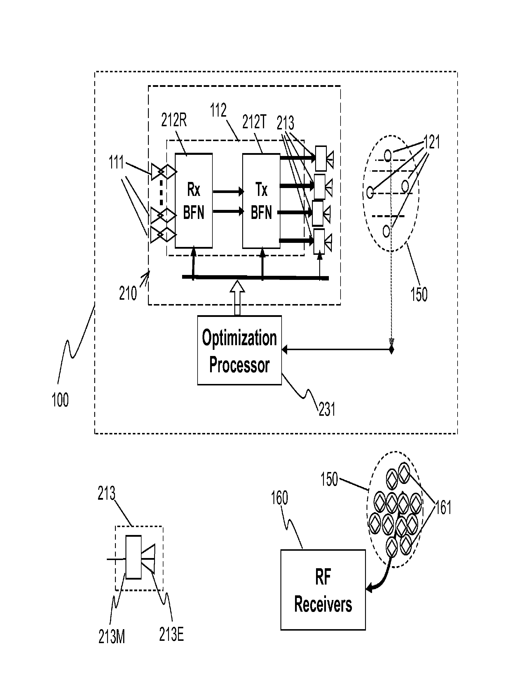
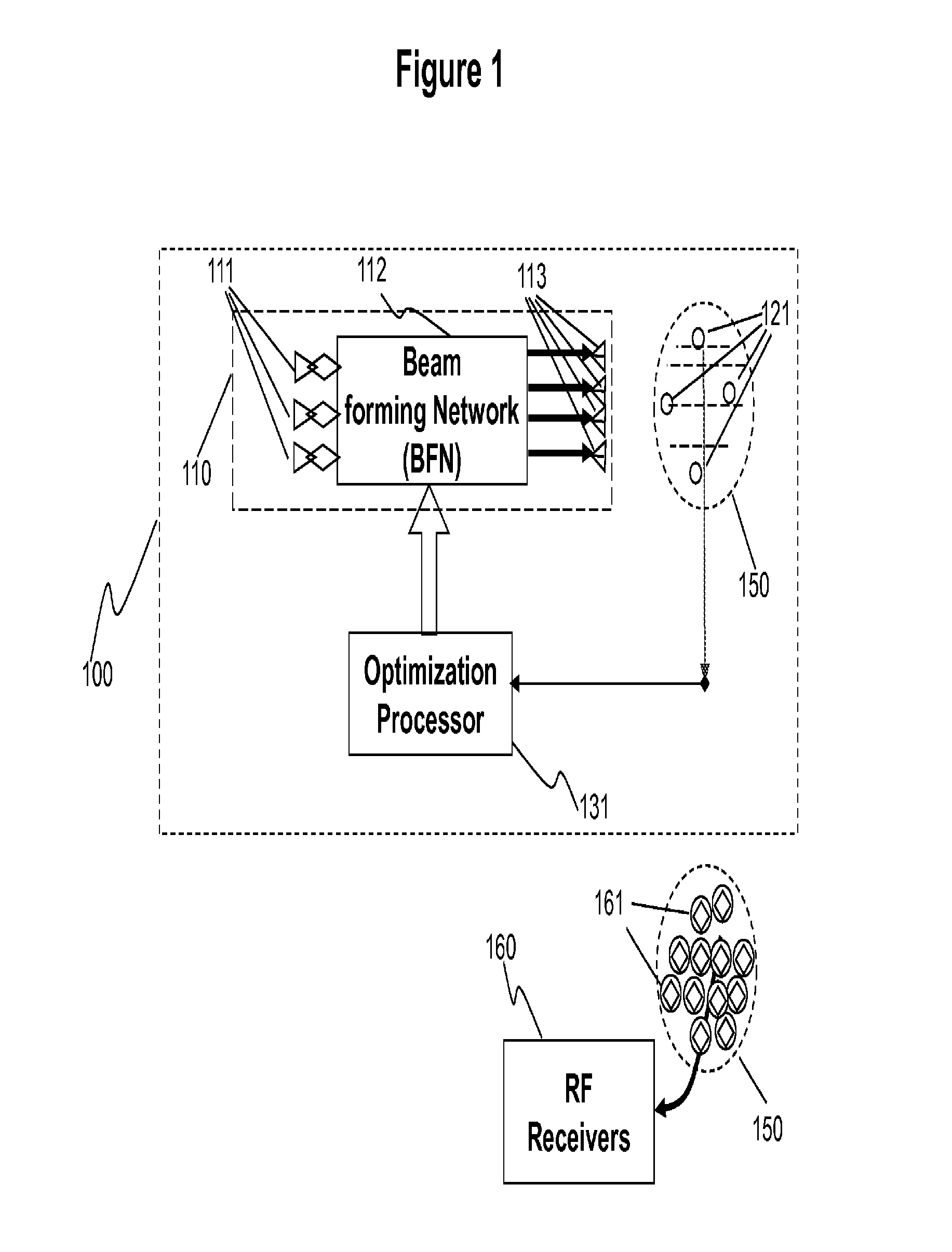
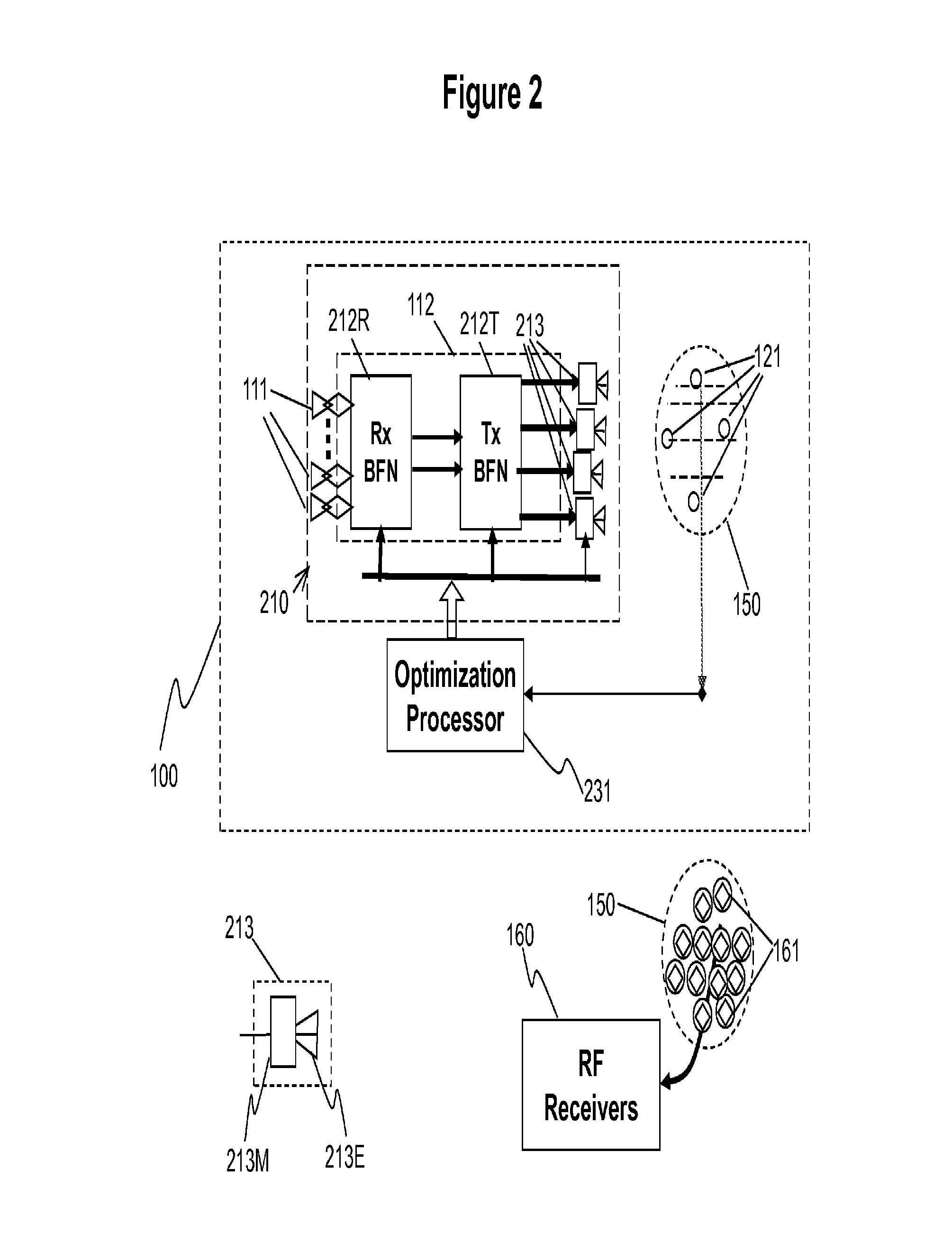
[0039]The proposed quiet zone generation technique features injection of interferences at low power levels for cancellations. The interference mitigation technique consists of an auxiliary injection array with iterative processing to dynamically maintain a quiet zone over limited areas over which Rx antenna apertures operating in full duplex while nearby Tx apertures with strong RF leakage are in operation.

[0040]In order to provide a working frame of reference, a glossary has been provided to define some terms used in the description and claims as a central resource for the reader. The glossary is intended to provide the reader with a general understanding of various terms as they are used in this disclosure, and is not intended to limit the scope of these terms. Rather, the scope of the terms is intended to be construed with reference to this disclosure as a whole and with respect to the claims below. Next, an overview is presented to provide a general understanding of the scope an...


PUM


Abstract

A quiet zone generation technique is proposed for interference mitigation for a receive antenna by injecting the very interference signals via iterative processing, generating quiet zones dynamically for receive (RCV) antennas. The receive antenna may feature multiple receiving apertures distributed over a finite area. Optimization loops consist of four cascaded functional blocks; (1) a pick-up array to obtain the interference signals, (2) element weighting and / or repositioning processors, (3) an auxiliary transmit (XMIT) array with optimized element positions, (4) a diagnostic network with strategically located probes, and (5) an optimization processor with cost minimization algorithms. To minimize interferences between transmit (Tx) and receiving (Rx) apertures in limited space of an antenna farm for communications and / or radar applications are very tough problems. However, solutions for co-site interference mitigation may not be generic ones but more specific to geometries of antenna farms, Tx apertures and Rx antenna locations, and beam positions of the Tx beams.

Description

RELATED APPLICATION DATABACKGROUND OF THE INVENTION[0001]1. Field of the Invention[0002]The present invention relates to architectures and designs of mitigation techniques for RF (radio frequency) systems against strong RF interferences.[0003]Strong leakage signals from nearby transmitters often saturate receiver front-ends of RF systems. The invention relates to (1) mitigation architectures and designs of self-jamming in antenna farms where transmitting (Tx) and receiving (Rx) apertures are adjacent to one another over limited space; such as cell phone base-stations, RF repeaters, mobile communications terminals, FMCW (frequency modulated continuous-wave) radars, RF systems on air mobile platforms, RF systems on ships, RF systems on satellites, and etc.[0004]On the other hand, strong external jamming signals often reduce sensitivity of RF receivers. This invention also relates to (2) mitigation architectures and designs of sensitive RF receivers against strong external jamming syst...

Claims


Application Information

Patent Timeline
Patent Type & Authority Patents(United States)
IPC IPC(8): H04K3/00G10K11/178
CPCG10K11/178G10K2210/12G10K2210/128G10K2210/3215G10K11/17857G10K11/348G01S19/215G10K11/34G10K11/341
Inventor CHANG, DONALD C. D.LIN, MICHAEL T. H.CHEN, STEVE
Owner SPATIAL DIGITAL SYST
Why Eureka
Try Eureka