
Acoustic-electric channel construction and operation using adaptive transducer arrays

a transducer array and adaptive technology, applied in the field of acoustics, can solve the problems of significant impact on the capabilities of the channel(s), significant reduction in power transfer efficiency, and reduced data communication rate, so as to minimize the footprint of such systems and achieve significant loss in channel quality and performan

Active Publication Date: 2016-11-22
RENESSELAER POLYTECHNIC INST
View PDF19 Cites 2 Cited by
  • Summary
  • Abstract
  • Description
  • Claims
  • Application Information

AI Technical Summary

Benefits of technology

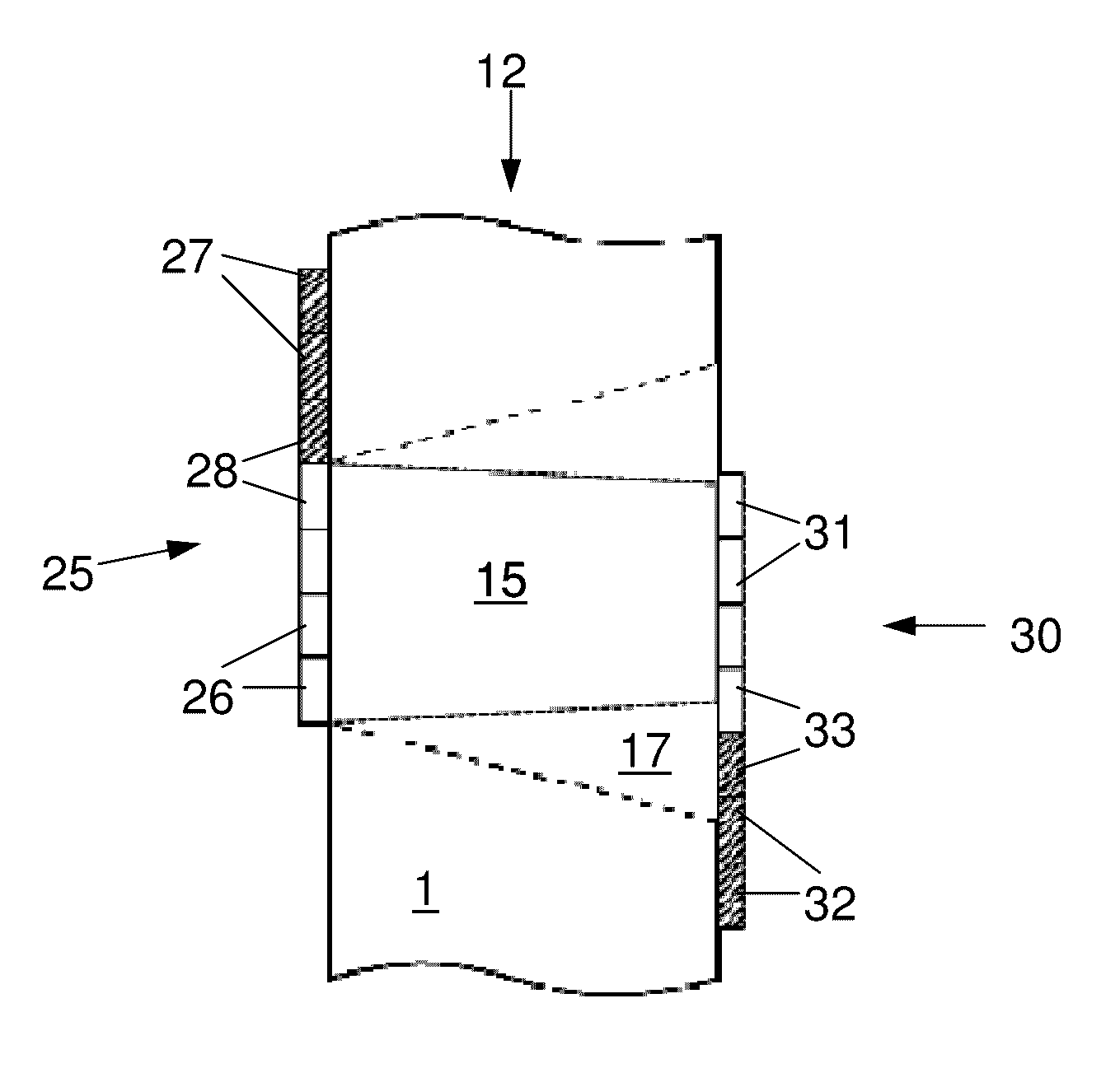
The present invention provides arrangements and methods to overcome problems caused by misaligned transducers, particularly transducer sets or arrays. This application also concerns the transfer of power and / or data through structures using acoustic-electric channels formed using piezoelectric transducers. The method allows for some amount of alignment error or variability in the transducer alignment without significant loss in channel quality and performance. This compensates for the inability to precisely align transmitting and receiving transducers across a non-trivial barrier interface. The method also discusses a means for the overlap of channel arrays constructed to transmit power and / or data, which is useful for minimizing the footprint of such systems. These methods are useful in applications where it is difficult to achieve perfect array alignment and in applications where the arrays are mounted on movable surfaces.

Problems solved by technology

One significant issue with transducer channel arrangement, including the above systems, is that the alignment of the transducers has a significant impact on the capabilities of the channel(s).
For power delivery, even a small amount of misalignment results in a significant reduction in power transfer efficiency.
Nevertheless, transducer misalignment can make the channel response more complex and can result in a reduced data communication rate.
Transducer installation and alignment can be much more difficult, however, when installations are done “in the field” or on previously fabricated structures.
In many “real world” implementations, transducer alignment can involve significant dimensional error due to scale, surface inaccessibility, surface irregularity, inability to see both sides of a barrier simultaneously, and other factors.
This situation would result in a significant loss in power transfer efficiency and / or potential communications performance loss, such as higher error rates or reduced data transfer rates.
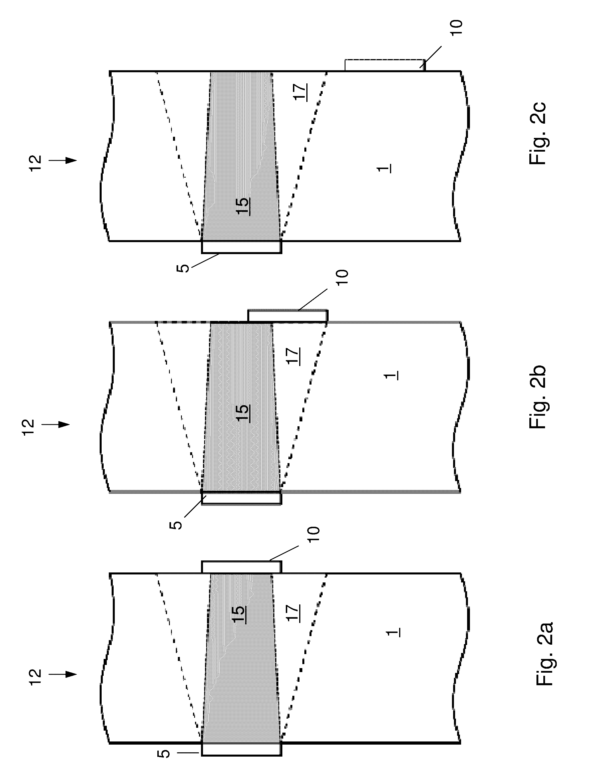
The third case, case©, shows the receive transducer completely misaligned with the transmit transducer, resulting in a severely degraded channel.
Nevertheless, given the losses associated with misalignment and the difficulty in achieving and / or maintaining alignment in some applications, methods and apparatus for optimizing operation despite transducer mis-alignment and alignment variability are needed.

Method used


Image

  • Acoustic-electric channel construction and operation using adaptive transducer arrays
  • Acoustic-electric channel construction and operation using adaptive transducer arrays
  • Acoustic-electric channel construction and operation using adaptive transducer arrays

Examples


Embodiment Construction

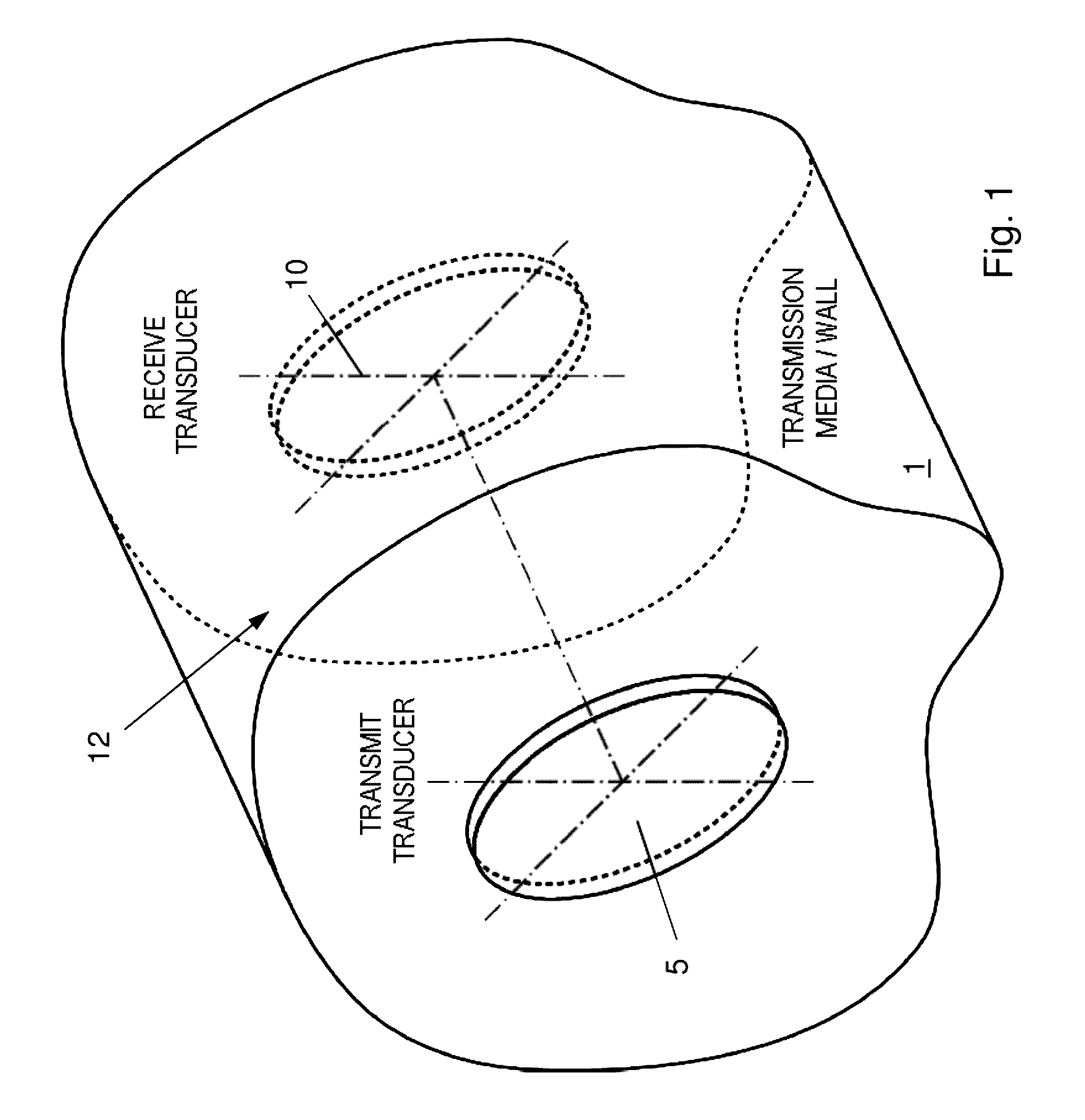
[0069]Referring now to the drawings, in which like reference numerals are used to refer to the same or similar elements, FIG. 1 shows an example of a simple piezoelectric-based acoustic-electric channel 12. A transmit transducer 5 and a receive transducer are axially aligned on opposite sides of a transmission wall 1. The pair of transducers 5,10 and the area of the wall between them 10, form the channel 12. In this example the transmit 5 and receive 10 transducers are circular “disk” transducers whose axes are coaxially aligned. Ideally, the transmit and receive transducer or transducers 5,10 are perfectly aligned across the wall although, as mentioned, such will not always be the case.

[0070]FIGS. 2a-2c illustrate three generalized alignment cases for a single pair of transducers, including a simplified representation of a hypothetical signal beam 15,17. Note that the diagrams show some spreading 17 of the acoustic energy beam 15 as the distance from the transmit transducer 5 incre...


PUM

PropertyMeasurementUnit
power transfer efficiencyaaaaaaaaaa
poweraaaaaaaaaa

Abstract

A method for transmitting power, data, and instructions using acoustic-electric channels having one or more transducer arrays, and to compensate for imperfect alignment of transducer arrays. Transducer arrays each include multiple transducer elements coupled to a channel barrier. Each element can be independently controlled, and misaligned transducers are selectively deactivated to improve overall channel performance. Arrays are optimized by testing different combinations of elements, and the combinations which are the most effective or efficient are used for transmissions. The system and the optimization features can be used to communicate between surfaces which have relative movement, such as between water craft hulls. Optimization can be periodic or constant to compensate for movement within the channel. The arrays can be used with curved substrates. Methods of designing adaptable arrays are also provided.

Description

CROSS-REFERENCE TO RELATED APPLICATION[0001]This application claims priority on U.S. provisional patent application 61 / 718,796 filed Oct. 26, 2012 which is incorporated herein by reference.FIELD AND BACKGROUND OF THE INVENTION[0002]The present invention relates generally to the field of acoustics, and in particular to transducers, to communication and power transmission using arrays of transducers, and to optimizing transducer performance when alignment is imperfect or when transducers may move over time.[0003]A transducer is a device that converts a signal in one form of energy to another form of energy. This can include electrical energy, mechanical energy, electromagnetic and light energy, chemical energy, acoustic energy, and thermal energy, among others. While the term “transducer” often refers to a sensor or a detector, any device which converts energy can be considered a transducer.[0004]Transducers are often used in measuring instruments. A sensor is used to detect a paramet...

Claims


Application Information

Patent Timeline
Patent Type & Authority Patents(United States)
IPC IPC(8): H04B11/00H04R17/00H04R31/00
CPCH04B11/00H04R17/00H04R31/00H04R2201/401Y10T29/49005
Inventor SAULNIER, GARY J.WILT, KYLE R.SCARTON, HENRY A.
Owner RENESSELAER POLYTECHNIC INST
Learn More