Carbon nanotube fiber cathode

a carbon nanotube and fiber cathode technology, applied in the direction of electric discharge tube/lamp manufacturing, non-electron-emitting electrode materials, discharge tube luminescnet screens, etc., can solve the problems of limited number of emission sites, limited current density of such large arrays, and difficulty in achieving high current densities of carbon nanotube cathodes. achieve high current densities and voltages, and achieve high current carrying capacity, the effect of superiority

Active Publication Date: 2014-07-01
GOVERNMENT OF THE UNTIED STATES
View PDF41 Cites 7 Cited by
  • Summary
  • Abstract
  • Description
  • Claims
  • Application Information

AI Technical Summary

Benefits of technology

[0005]The disclosed field emission cathodes overcome these limitations and provide superior, unprecedented performance in high energy applications. They handle much higher current densities and voltages than existing carbon nanotube field emission cathodes while suffering minimal damage and performance loss. The field emission cathodes disclosed herein comprise fibers of highly aligned, densely packed single-walled carbon nanotubes (SWNTs). These fiber cathodes provide superior current carrying capability without degradation or adverse effects under high field strength testing. Cathodes can be configured as single fibers or multiple fibers. Use of coatings and different field tip configurations further improves the performance of these fiber cathodes that provide heretofore unachievable currents in field emission cathodes and maintain this level of performance indefinitely without degradation or loss of performance.

Problems solved by technology

Although a single carbon nanotube can emit over 1 μA, obtaining high current densities from a large area carbon nanotube cathode is difficult to achieve.
The problem with large area carbon nanotube cathode films comprising a plurality of individual carbon nanotubes is that the number of emission sites is limited by screening effects of the individual nanotubes and this in turn limits the current density of such large arrays.
Currents also can be unstable under high field strengths.
These limitations have prevented the realization of macroscopic carbon nanotube cathodes for high energy vacuum electronic applications.
Each of these applications typically requires high current densities with a high brightness electron beams driven by cathodes exhibiting long lifetime in the presence of deleterious conditions such as ion back bombardment and excessive heating.
Small diameter (<50 μm) graphite fibers have been studied for these applications but they have not demonstrated the required robustness.
They typically suffer serious degradation due to joule heating and produce at the most several hundred microamps before failure after tens of hours of operation.
Similarly, carbon nanotube yarns that are spun from largely unaligned, multi-wall nanotubes are not durable enough for use as field emission cathodes due to their low density and the fact that they quickly degrade under high field testing.

Method used


Image

  • Carbon nanotube fiber cathode
  • Carbon nanotube fiber cathode
  • Carbon nanotube fiber cathode

Examples


Embodiment Construction

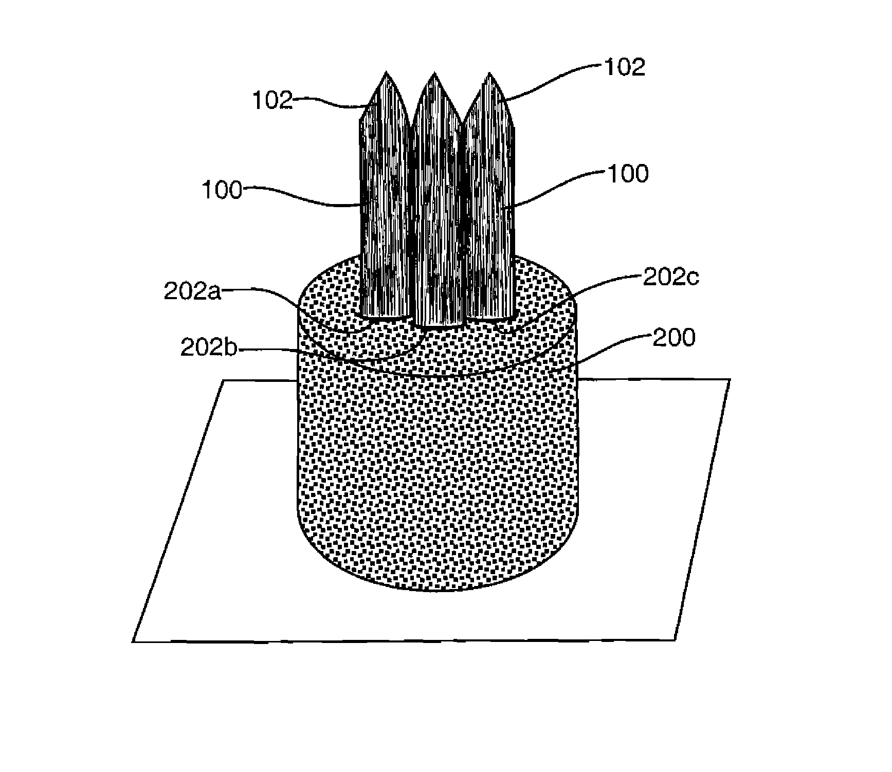
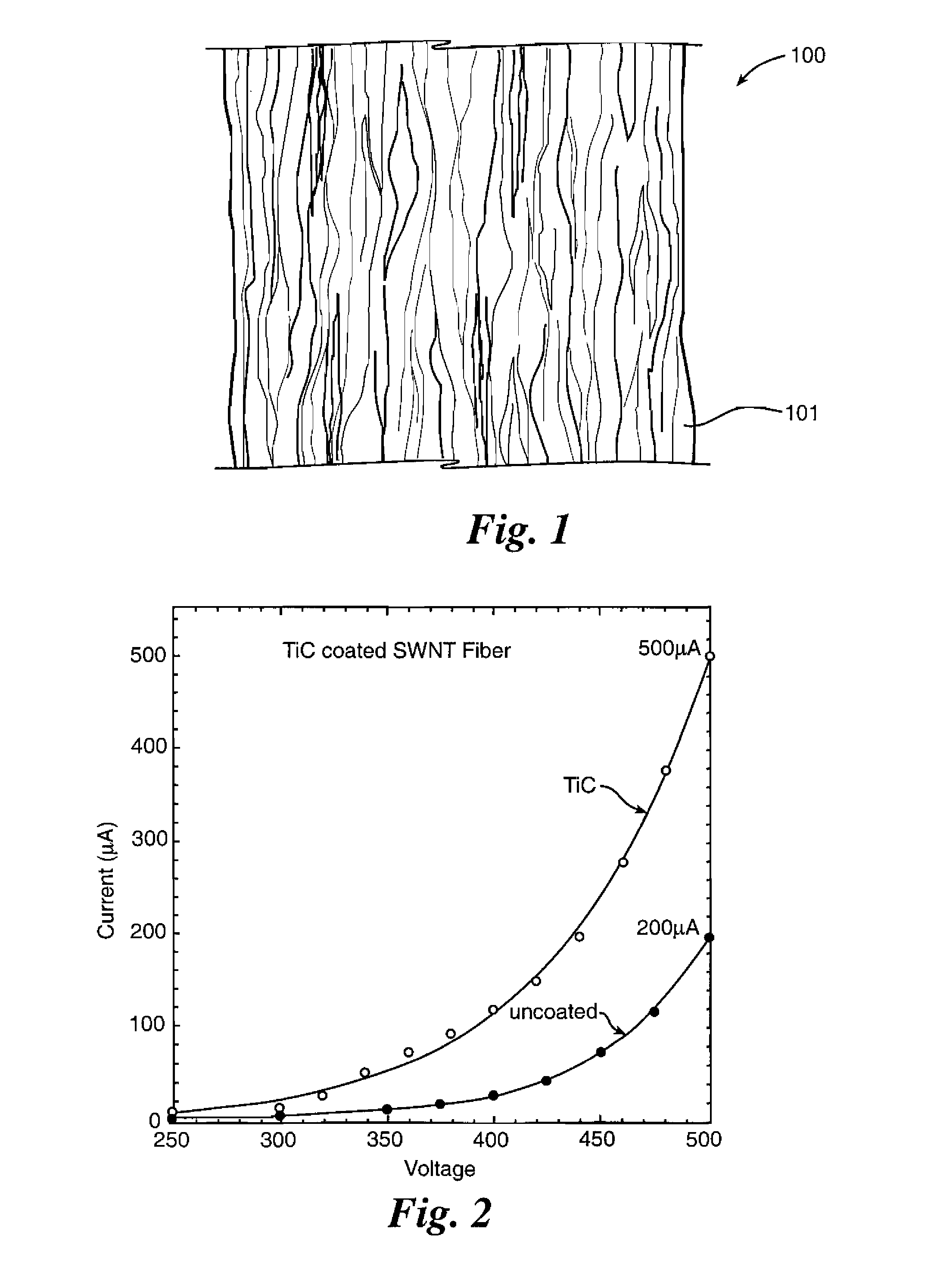
[0020]The disclosed fiber cathodes may be formed from a variety of materials. They may be formed from single-wall nanotubes (SWNTs) by spinning solutions of SWNTs in a superacid into different coagulants to form a fiber, as disclosed in U.S. Pat. No. 7,125,502 B2, the entire contents of which are incorporated herein by reference. As shown in FIG. 1, such a fiber 100 comprises a plurality of densely-packed SWNTs 101 that are highly-aligned along an axial direction of the fiber 100. The fiber 100 can have varying diameters depending on the number of SWNTs that are spun together and may be, for example, about 40 to 400 microns in diameter and have carbon nanotube densities of about 50% to about 100% and preferably of about 70% to about 100% of the theoretical maximum density of nanotubes. The fiber 100 may comprise a plurality of densely-packed double-wall carbon nanotubes, multi-wall carbon nanotubes, graphene nanoribbons, and / or carbon nanofibers in addition to, or in lieu of, the SW...


PUM

PropertyMeasurementUnit
currentaaaaaaaaaa
diameteraaaaaaaaaa
diameteraaaaaaaaaa

Abstract

Improved field emission cathodes comprise a fiber of highly aligned and densely packed single-wall carbon nanotubes, double-wall carbon nanotubes, multi-wall carbon nanotubes, grapheme nanoribbons, carbon nanofibers, and/or carbon planar nanostructures. The fiber cathodes provide superior current carrying capacity without degradation or adverse effects under high field strength testing. The fibers also can be configured as multi-fiber field emission cathodes, and the use of low work function coatings and different tip configurations further improves their performance.

Description

CROSS-REFERENCE TO RELATED APPLICATIONS[0001]This application claims the benefit of U.S. Provisional Application No. 61 / 350,624, which was filed in the U.S. Patent and Trademark Office on Jun. 2, 2010.RIGHTS OF THE GOVERNMENT[0002]The invention described herein may be manufactured and used by or for the Government of the United States for all governmental purposes without the payment of any royalty.BACKGROUND[0003]Carbon nanotubes are used as electron sources due to their large aspect ratio, high conductivity, and the low field strengths needed to extract current. Among their uses is as field emission cathodes. Typical cathode arrangements involve films consisting of tangled, spaghetti-like carbon nanotubes or loose carpets of vertically aligned carbon nanotubes that have a typical density of 1-5% of their theoretical maximum density. Both configurations are derived from catalyst-induced growth of carbon nanotubes on a substrate. Although a single carbon nanotube can emit over 1 μA,...

Claims


Application Information

Patent Timeline
Patent Type & Authority Patents(United States)
IPC IPC(8): H01J29/46H01J1/28H01J1/14H01J1/304
CPCH01J11/40H01J29/467H01J2329/0431H01J2201/30469H01J1/28H01J1/304H01J2201/3043H01J9/025H01J2201/304H01J25/34H01J1/3042H01J2329/0455
Inventor FAIRCHILD, STEVEN BMARUYAMA, BENJI
Owner GOVERNMENT OF THE UNTIED STATES
Why Eureka
Try Eureka