
Orientation device for orientating a sensor probe

a sensor and probe technology, applied in the direction of instruments, manufacturing tools, metal-working machine components, etc., can solve the problems of high cost of detection means

Active Publication Date: 2016-11-29
GAZTRANSPORT & TECHNIGAZ
View PDF5 Cites 1 Cited by
  • Summary
  • Abstract
  • Description
  • Claims
  • Application Information

AI Technical Summary

Benefits of technology

The invention aims to create a device that can easily, cheaply, and successfully measure the normal of a surface. The device should be durable and able to measure the normal of a surface in real-time.

Problems solved by technology

However, this type of automatic machine requires computation means to determine the tangent to the profile and thus orient the welding torch according to this tangent.
Furthermore, these types of detection means are costly and can even be sensitive to electromagnetic disturbances.

Method used


Image

  • Orientation device for orientating a sensor probe
  • Orientation device for orientating a sensor probe
  • Orientation device for orientating a sensor probe

Examples


Embodiment Construction

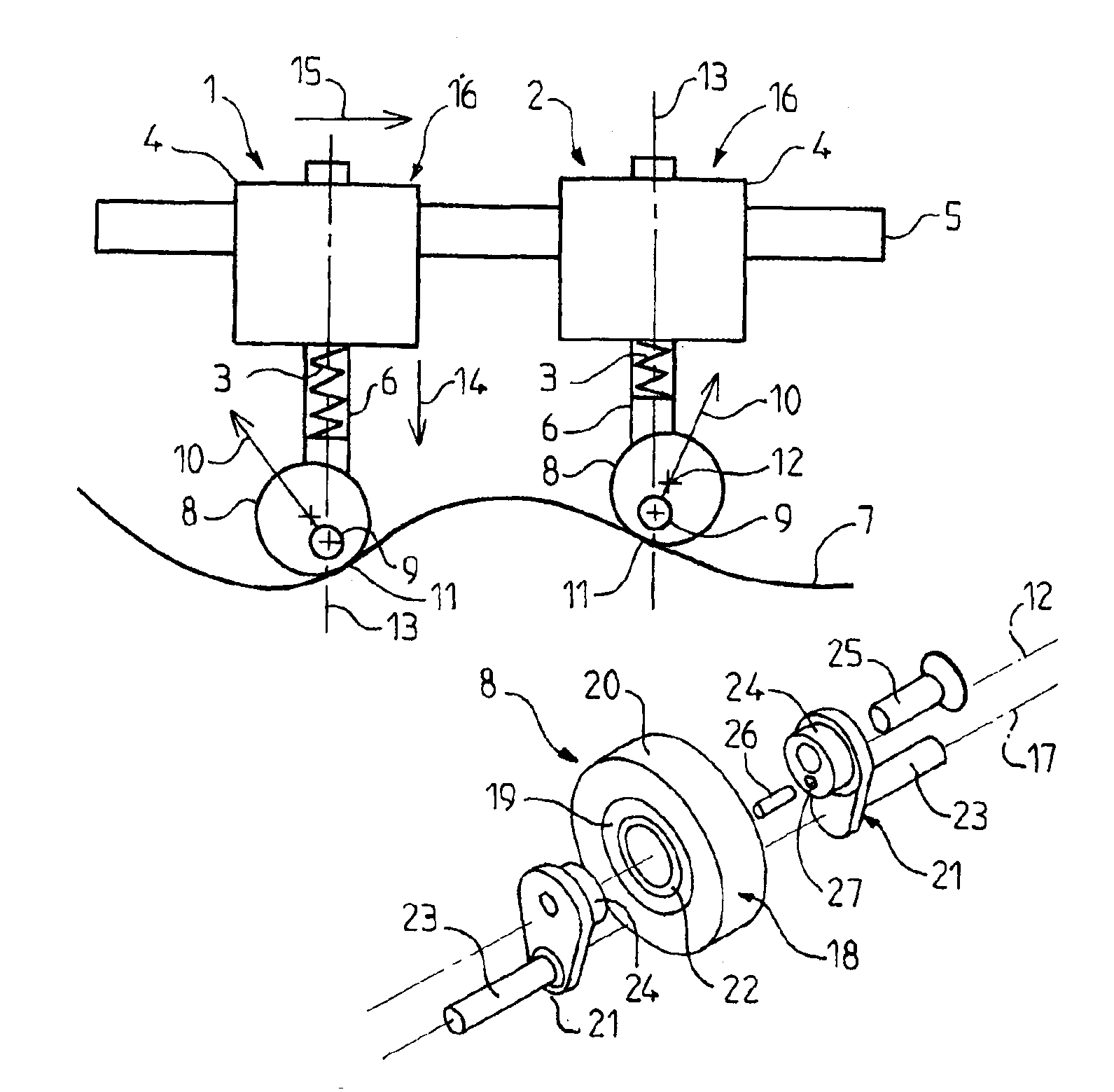
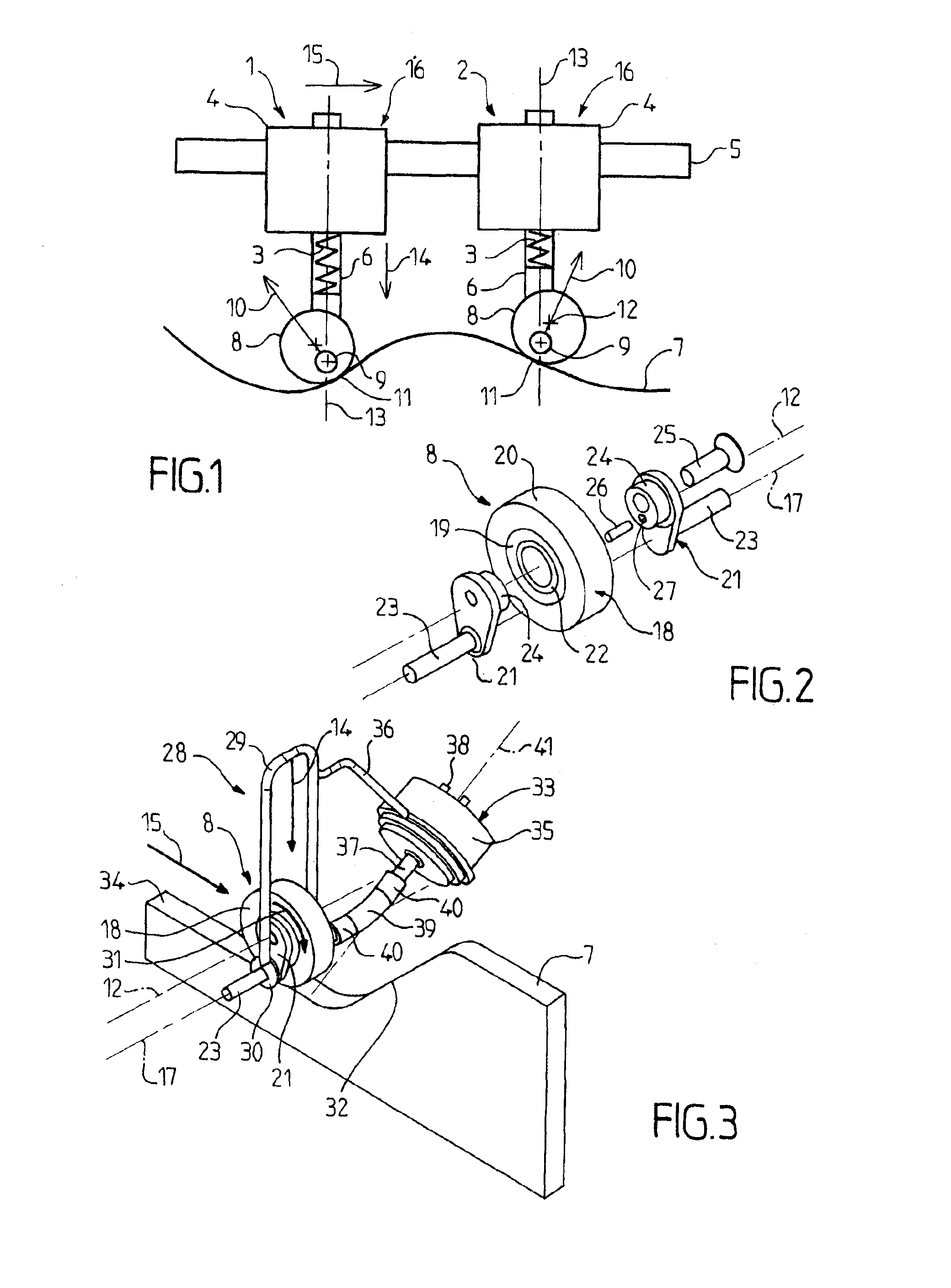
[0056]FIG. 1 shows a sensor carriage 16 moving on a guiding rail 5 over a measured surface 7. The sensor carriage 16 is represented in FIG. 1 in two positions 1 and 2 corresponding to two successive positions reached by the sensor carriage 16 in its movement on the guiding rail 5 in a direction of advance 15 defined by the orientation of the guiding rail 5.

[0057]The sensor carriage 16 comprises a frame 4 in which actuators can set a pinion in motion. The pinion is engaged with a rack securely attached to the rail 5. This rack extends in the direction of the rail 5. Thus, when the actuators drive the pinion in rotation, the latter cooperates with the rack to provoke the movement of the sensor carriage 16 in the direction of advance 15. The driving can also be produced by notched belt, cable, pressed rolling, cylinder or linear motor.

[0058]A bearing arm 6 is mounted to slide relative to the frame 4 of the sensor carriage 16 along a sliding axis 13 at right angles to the direction of a...


PUM


Abstract

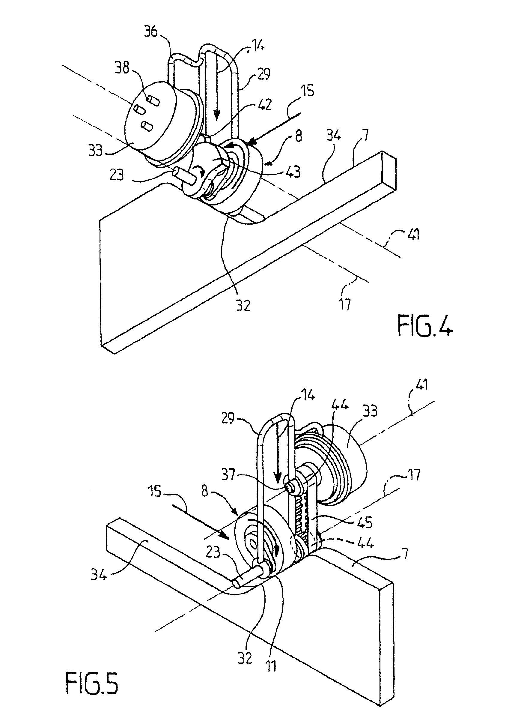
A device for orientating a sensor probe relative to the local normal vector of a work surface, the device comprising: a frame, a moving support element linked to the frame and able to slide in a predetermined direction, a sensor probe able to pivot on an axis of rotation not parallel to the predetermined direction relative to a point of articulation of the support element, pressure means able to move and generate a force on the moving support element in predetermined direction so as to press the sensor probe against the work surface, in which the sensor probe comprising a single convex external sensing surface suitable for being placed in contact with the work surface, the sensing surface having a single equilibrium contact point, the equilibrium contact point being the point on the sensing surface closest to the point of articulation.

Description

CROSS-REFERENCE TO RELATED APPLICATIONS AND CLAIM TO PRIORITY[0001]This application is a national stage application of International Application No. PCT / FR2013 / 050426 filed Feb. 28, 2013, which claims priority to French Patent Application No. 1251955 filed Mar. 2, 2012, of which the disclosures are incorporated herein by reference and to which priority is claimed.FIELD OF THE INVENTION[0002]The invention relates to the field of tools for mechanically measuring the normal of a surface. For example, the present invention relates to tools for following the normal of a surface to guide work tools relative to the surface.BACKGROUND OF THE INVENTION[0003]Tools for following the normal of a surface can be used to guide a welding torch for the welding of metal plates, for example, to produce a sealed tank wall.[0004]Such a sealed tank is obtained by welding together metal parts which have a common profile. FR2701415 describes an automatic machine which is capable of producing welds followin...

Claims


Application Information

Patent Timeline
IPC IPC(8): B23Q17/20B23Q17/22B23Q35/08G01D11/30B23Q35/26
CPCB23Q17/20B23Q35/26G01D11/30
Inventor MENARD, GEORGESLECOURTOIS, PIERRELAURAIN, NICOLASDELETRE, BRUNO
Owner GAZTRANSPORT & TECHNIGAZ
Learn More