Electrolysis cell and electrolysis tank

a technology of electrolysis cell and electrolysis tank, which is applied in the direction of electrolysis components, electrolysis coatings, coatings, etc., can solve the problems of easy cathode oxidation, high cost of electrolysis, and easy cathode degradation

Active Publication Date: 2016-11-29
ASAHI KASEI KK
View PDF18 Cites 4 Cited by
  • Summary
  • Abstract
  • Description
  • Claims
  • Application Information

AI Technical Summary

Benefits of technology

[0035]According to the invention, an electrolysis cell capable of suppressing the degradation of a cathode by the reverse current at the time of stopping electrolysis and an electrolysis tank are provided.

Problems solved by technology

Along with it, the reverse current (current flowing in the direction opposite to the electrolytic current) generated at the time of stopping has increased, and thus the degradation due to the oxidation of the cathode easily occurs.
However, there is a problem that the cost of electrolysis increases since the operation is complicated and incidental facilities are required in this electrolysis stopping method of applying the protection current.

Method used


Image

  • Electrolysis cell and electrolysis tank
  • Electrolysis cell and electrolysis tank
  • Electrolysis cell and electrolysis tank

Examples


first embodiment

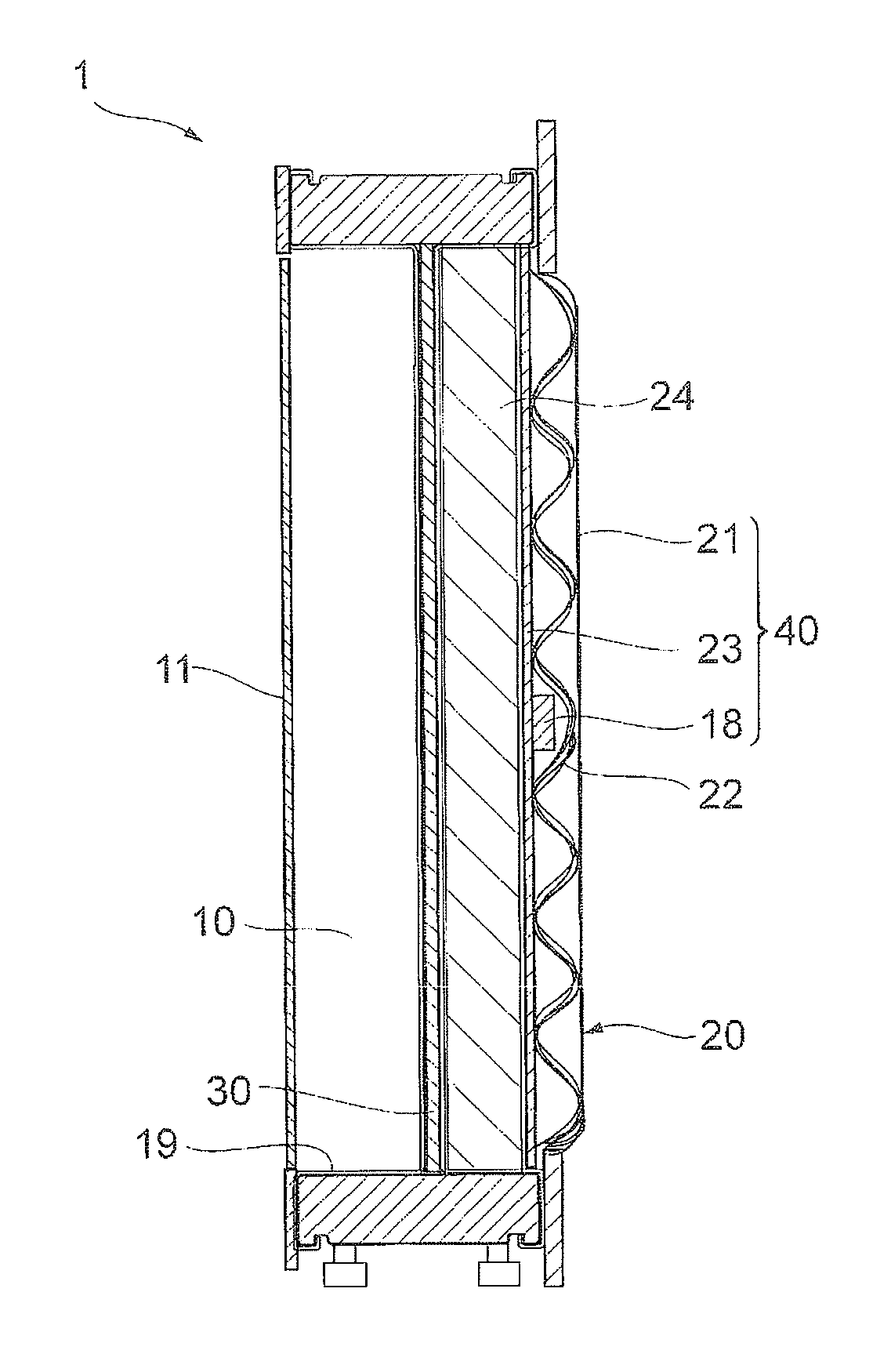
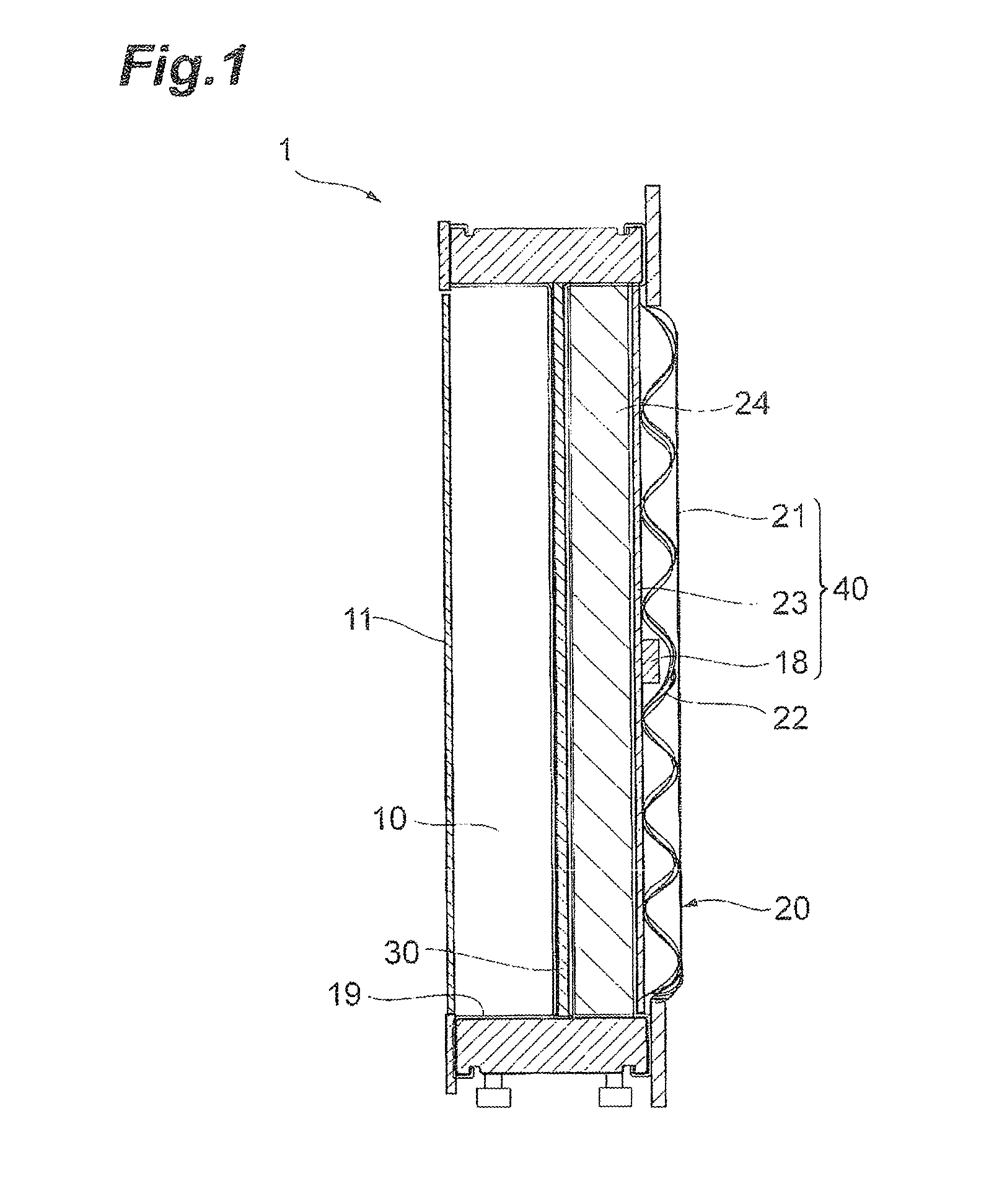
[0046]FIG. 1 is a cross-sectional view of an electrolysis cell 1 of a first embodiment of the invention. The electrolysis cell 1 is equipped with an anode chamber 10, a cathode chamber 20, a partition wall 30 installed between the anode chamber 10 and the cathode chamber 20, an anode 11 installed in the anode chamber 10, a cathode 21 installed in the cathode chamber 20, a reverse current absorbing body 18 having a substrate 18a and a reverse current absorbing layer 18b formed on the substrate 18a and installed in the cathode chamber. The anode 11 and the cathode 21 belonging to one electrolysis cell 1 are electrically connected. In other words, the electrolysis cell 1 is equipped with the following cathode structure. A cathode structure 40 is equipped with the cathode chamber 20, the cathode 21 installed in the cathode chamber 20, and the reverse current absorbing body 18 installed in the cathode chamber 20, and the reverse current absorbing body 18 has the substrate 18a and the rev...

second embodiment

[0136]A second embodiment is the same as the first embodiment except the following differences. Hereinafter, only the differences between the first embodiment and the second embodiment will be described, and the description on the common subject matters of both embodiments will be omitted. According to the second embodiment, it is possible to suppress the oxidation and degradation of the cathode in the same manner as the first embodiment.

[0137]FIG. 6 is a cross-sectional view of the electrolysis cell 1 according to the second embodiment. The electrolysis cell 1 according to the second embodiment is different from the electrolysis cell 1 according to the first embodiment in that a metal elastic body and a current collector are not equipped therein. The cathode chamber 20 equipped in the electrolysis cell 1 of the second embodiment has a support 24 disposed between a cathode 21 and a partition wall 30. The support 24 supports the cathode 21. The partition wall 30 is electrically conne...

example 1

[0142]The surface of nickel expanded metal (substrate) was plasma sprayed with nickel oxide powder, thereby coating the substrate with nickel oxide powder (reverse current absorbing layer). Nitrogen was used as the primary gas for the plasma spraying and hydrogen was used as the secondary gas. The electrolysis of salt to generate hydrogen was performed using the substrate coated with the reverse current absorbing layer as the cathode. The reverse current absorbing body of Example 1 was obtained through the reduction treatment by the electrolysis. Meanwhile, the conditions at the time of the electrolysis were as follows.

Current density: 4 kA / m2, electrolysis temperature: 90° C., and concentration of sodium hydroxide: 32% by weight.

[0143](Evaluation on Reverse Current Absorption)

[0144]The reverse current absorbing body was cut into a size of 3 cm×3 cm and fixed to a nickel rod coated with PTFE with nickel screws. A platinum plate was used as the counter electrode (anode).

[0145]The rev...


PUM


Abstract

Provided is an electrolysis cell capable of suppressing the degradation of a cathode by the reverse current at the time of stopping electrolysis. According to an aspect of the invention, there is provided an electrolysis cell comprising an anode chamber, a cathode chamber, a partition wall separating the anode chamber from the cathode chamber, an anode installed in the anode chamber, a cathode installed in the cathode chamber, and a reverse current absorbing body having a substrate and a reverse current absorbing layer formed on the substrate and installed in the cathode chamber, in which the anode and the cathode are electrically connected and the cathode and the reverse current absorbing layer are electrically connected.

Description

TECHNICAL FIELD[0001]The present invention relates to an electrolysis cell for the electrolysis of an alkali salt, the water electrolysis, and a fuel cell, and an electrolysis tank.BACKGROUND ART[0002]An ion exchange membrane method using an electrolysis tank equipped with an ion exchange membrane is mainly used in the electrolytic decomposition (hereinafter, referred to as the “electrolysis”) of an aqueous solution of alkali metal chloride such as brine. This electrolysis tank is equipped with a large number of electrolysis cells connected in series therein. Electrolysis is performed by interposing an ion exchange membrane between the respective electrolysis cells. A cathode chamber having a cathode and an anode chamber having an anode are disposed back to back via a partition wall (rear plate) in the electrolysis cell. As an electrolysis tank, an electrolysis tank described in Patent Literature 1 or the like is known.[0003]In recent years, the facility of an electrolysis tank has ...

Claims


Application Information

Patent Timeline
Patent Type & Authority Patents(United States)
IPC IPC(8): C25B1/46C25B9/08C25B11/04C25B9/19
CPCC25B9/08C25B1/46C25B11/04C25B9/19C25B9/23C25B11/046C25B11/085C23C4/04C23C4/18
Inventor FUNAKAWA, AKIYASUHACHIYA, TOSHINORI
Owner ASAHI KASEI KK
Why Eureka
Try Eureka