Cage for breeding small animals

a cage and small animal technology, applied in the field of cages for breeding small animals, can solve the problems and reducing the number of qualified animals, so as to reduce labor and reduce the cost of facility and maintenance costs for animal testing, the effect of reducing the number of parts

Active Publication Date: 2016-12-06
EATRON
View PDF20 Cites 1 Cited by
  • Summary
  • Abstract
  • Description
  • Claims
  • Application Information

AI Technical Summary

Benefits of technology

[0055]The cage for breeding small animals according to the present invention is a closed system, in which a lid is provided on an opening part of the casing and a water supply apparatus is attached in an openable and closable fashion to an opening part for the water supply apparatus provided on the lid. Thus, pathogenic bacteria of small animals in the cage (in case where the small animals hold any pathogenic bacteria) will not infect small animals in other cages or will not contaminate the facility.
[0056]Furthermore, according to the present invention, a partition board is placed within the casing in such a manner to divide a housing section of the casing into a left room and a right room, and a ventilation section for ventilation between the two rooms is provided in the partition board. Thereby, air flows from one room of the housing sections through the ventilation section to the other within the casing. Furthermore, a communicating section for placing a tip of a nozzle of the water supply apparatus is provided in the partition board, thus allowing small animals housed in both one room and the other room of the housing section to drink water from the common water supply nozzle. Because of this, if the small animal housed in the other room of the housing section is infected, it becomes possible to detect that the small animal in the one room of the housing section is also infected with some pathogenic bacteria through aerial infection and / or oral infection.
[0057]In particular, when an air pipe faces one room of the housing section within the casing and an exhaust pipe faces the other room of the casing, the air introduced into one room of the casing from the air pipe flows through the ventilation section to the other room of the casing, and the air is then exhausted from the exhaust pipe. As described above, a ventilation path for air is formed within the cage, and pathogenic bacteria of the small animal bred in the upstream side of the housing section readily infect the small animal bred in the downstream side of the housing section.
[0058]Besides the ventilation section opened through the partition board, the partition board comprises a shielding section formed with a region other than the opening for dividing the space in the casing into two and shielding the border between one room and the other room. When the area of the open ventilation section accounts for 10 to 50% of the area of the partition board, and even if the amount of air and the velocity of the air introduced into the cage is reduced, air blown into one of the spaces is guided to the other space by the shielding section via the ventilation section, causing air flow within the cage and allowing inside the cage to be fully ventilated. Thus, this allows a ventilation apparatus, which is connected to the cage from outside the cage, to be miniaturized.
[0059]Furthermore, the casing is configured with a double casing of an outer case and an inner case, a bottom portion of the inner case is engaged with a bottom portion of the partition board, and the inner case is engaged with the outer case. Thus, the casing can be transported while small animals are housed within the inner case, and the inner case can be disposed of when it becomes dirty. In such a manner, facility and maintenance costs required for animal testing can be minimized, resulting in reducing labor. Furthermore, the inner case can be maintained at a certain degree of cleanness.
[0060]Furthermore, in a case where a gripping member facing the opening part for the water supply apparatus is attached to a lower surface of the lid, the gripping member is exposed to the opening when the water supply apparatus is opened. Thus, the tail of the small animal within the casing can be pinched using the fingers or the like from the opening, and the small animal can be allowed to hold on to the gripping member, which makes it possible to securely perform manual immobilization on such small animals during collection of a blood sample or the like from the small animals, which are sensing the presence of humans and are afraid. Since the gripping member is placed on the inside of the lid, contaminants adhered to the gripping member will not be released to the outside air. Furthermore, since an internal mesh, a conventionally used separate member, is not used, the number of parts can be reduced.

Problems solved by technology

Thus, there occur variations in the microbiological quality of such small animals, which have great and negative influences on research and experiments and which also causes problems regarding qualification of small animals that may be used as a subject of research or experimentation.
For example, if small animals contaminated with pathogenic microbes are brought to a facility, the entire facility will be a new source of contamination, and for cleaning the facility, it will cost several hundred million yen and take labor to dispose of all the small animals and to disinfect and improve the facility.
Furthermore, a time loss of between three months and nearly a year is required for the cleaning of the facility environment and causes a very great deal of lost progress to research.
However, this certificate merely indicate under what conditions such small animals being delivered were bred, and never guarantees the microbiological quality of the individual small animals.
The subject animals are bred in various different environments and brought into research institutions as animals with a specific quality; however, it is not certain whether that would be true.
As a result, a problem of infection to other subject animals will occur, which may reduce the accuracy of biological experiments with the other subject animals.
While this apparatus can detect pathogenic microorganisms of the infected animals in the monitoring room, it is not possible, however, to specify which animal is the source of infection because the animals have been infected through air that has passed through all the small animals in a plurality of racks.
Furthermore, it is feared small animals in other adjacent cases will also be infected.

Method used


Image

  • Cage for breeding small animals
  • Cage for breeding small animals
  • Cage for breeding small animals

Examples


example 1

[0084]As illustrated in FIG. 16, a cage 2 for breeding small animals according to the present invention is mounted in a small animal breeding rack 60 in such a manner that the cage 2 can be inserted and removed through an opening formed on the front side of the rack 60. The rack 60 comprises a rectangular parallelepiped, frame body 61 formed of angles or the like, and a shelf frame 62 for dividing the space of the frame body 61 from top to bottom into a plurality of shelves. A plurality of breeding cages 2 are placed or supported in a suspended manner within a plurality of breeding spaces 63 formed on an upper part of each of the shelf frames 62. Each breeding space 63 has an opening on the front side, and the cage 2 is placed from the opening into the space 63 in such a manner that the cage 2 can be removed from the front.

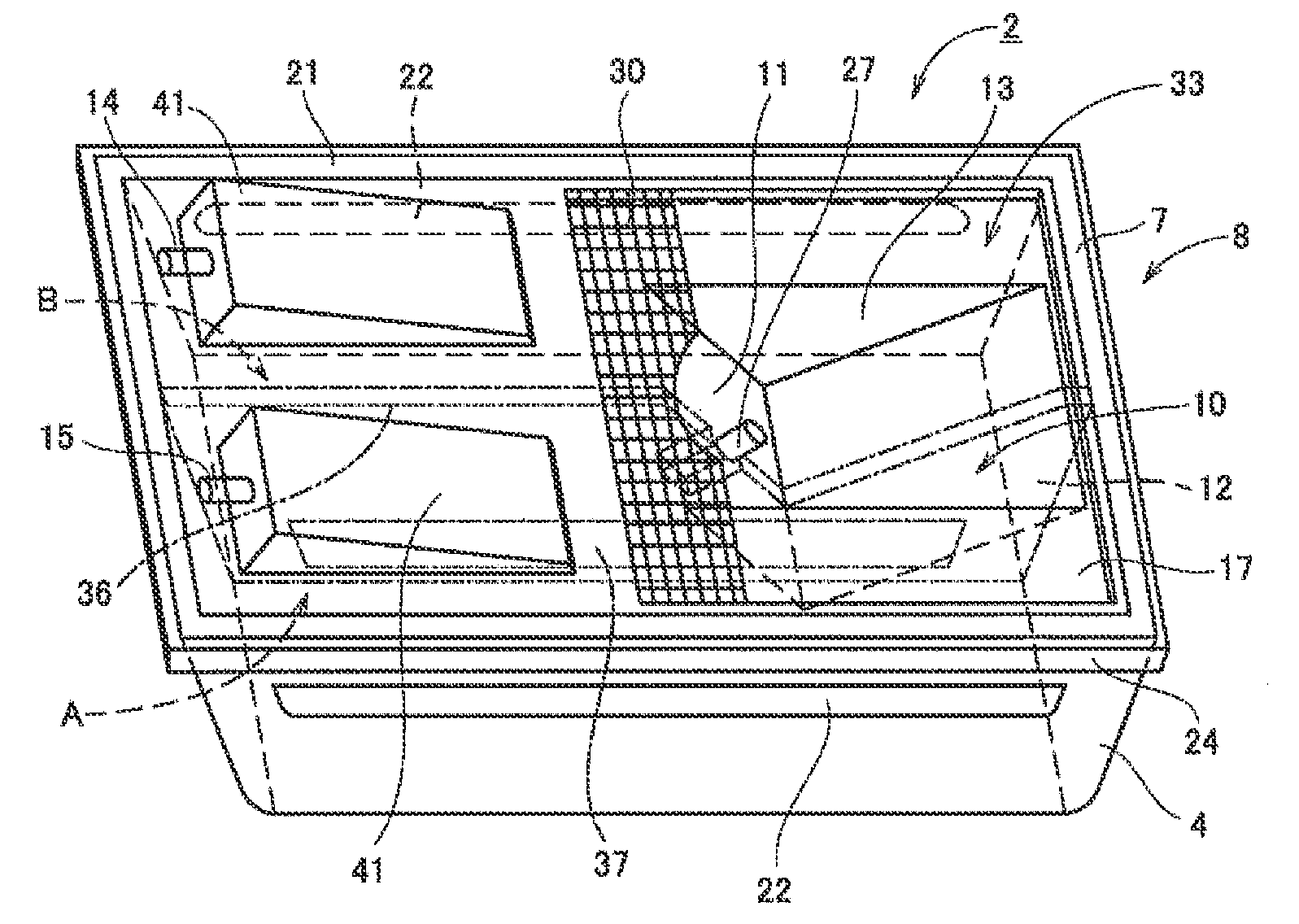
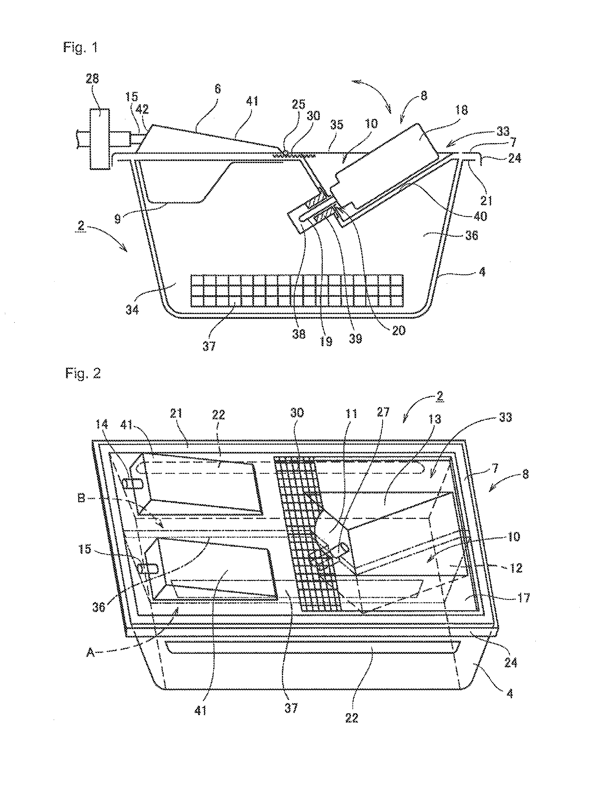
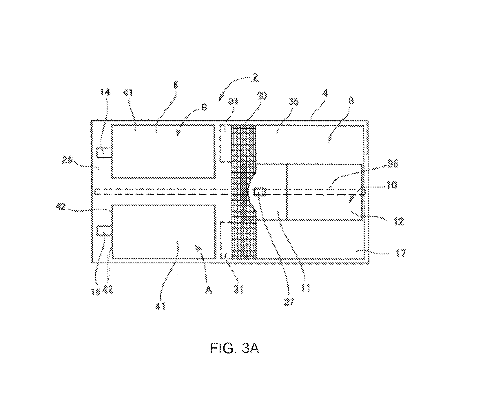
[0085]As illustrated in FIGS. 1 to 4, the cage 2 comprises: a rectangular parallelepiped, casing 4 with an opening on an upper surface thereof; a lid 6 for coveri...

embodiment 2

[0120]While a partition board 36 is placed within a single casing 4 in the embodiment described above, the casing 4 may be constituted of an outer case 46 and an inner case 43 and a partition board 36 may be placed within the inner case 43.

[0121]In such a case, as illustrated in FIGS. 11 to 13, an engaging protrusion 44 for retaining a partition board 36 is provided at each of both side ends on a bottom portion of the inner case 43. An engaging recess section 45, which can engage with the engaging protrusion 44, is provided at each of both side ends of a bottom portion of the partition board 36. In addition, a protrusion 47 is provided at each of both side ends on a bottom portion of the outer case 46, and the protrusion 47 can engage with a recess portion provided on a bottom surface side of the engaging protrusion 44 of the inner case 43.

[0122]With such a configuration, it becomes possible to attach the partition board 36 easily in a state where the partition board 36 is standing ...

embodiment 3

[0128]FIG. 15 illustrates a still another embodiment of the present invention.

[0129]In the present embodiment, a lid 6 for covering an opening on an upper surface of a casing 4 is attached in an openable and closable fashion to a part of the opening, and a water supply apparatus 8 is attached on a different part of the opening.

[0130]A shaft section 25 is formed at an end portion of the lid 6. A shaft bearing (not shown) is formed at an upper edge in the substantially middle part of the casing 4. The shaft bearing engages with the shaft section 25. The engagement of the shaft section 25 of the lid 6 with the shaft bearing allows the lid 6 to be supported pivotable upward and downward with respect to the lid 6.

[0131]A gripping member 30 is supported in a cantilever fashion with a water supply apparatus 8 located therebelow, and most of the gripping member 30 is placed below the lower surface of the lid 6. When the lid 6 is pivoted upward, the gripping member 30 is exposed from the ope...


PUM


Abstract

The cage for breeding small animals according to the present invention comprises a casing with an opening on an upper surface thereof, and a lid for covering the opening of the casing. The lid comprises a frame body attached to an upper end edge of the casing, and an opening for a water supply apparatus to which the water supply apparatus is attached in an openable and closable fashion. A partition board is placed in the casing to divide the housing section within the casing into two. A ventilation section is provided in the partition board, for ventilation between one room and the other room of the divided housing section in the casing. A communicating section for placing a tip of a nozzle of the water supply apparatus is provided by cutting out the partition board.

Description

CROSS-REFERENCE TO RELATED APPLICATIONS[0001]This application is continuation in part of PCT / JP2012 / 002441 filed on Apr. 6, 2012, which claims priority from Japanese Application No. 2011-250776 filed on Nov. 16, 2011, both of which are incorporated herein by reference.TECHNICAL FIELD[0002]The present invention relates to a cage for breeding small animals on the basis of novel and revolutionary ideas. Specifically, the present invention relates to a closed-system cage for breeding small animals, used for breeding small animals such as rats, mice, and guinea pigs in isolation, such that in a case of providing genetically-modified small animals for a biological experiment or the like, the cage is capable of allowing for the quality of such small animals to be confirmed or guaranteed, such that the animal is not infected with any pathogenic bacteria or the like, and if the animal is infected with such pathogenic bacteria, the presence of the pathogenic bacteria is detected. More specifi...

Claims


Application Information

Patent Timeline
Patent Type & Authority Patents(United States)
IPC IPC(8): A01K1/02A01K1/03A01K7/00
CPCA01K1/03A01K1/031A01K7/00
Inventor OSHIMA, SHIGERUOSHIMA, YOSHIKOMAKI, SATORU
Owner EATRON
Why Eureka
Try Eureka