Tamping wheel

a tamping wheel and wheel body technology, applied in the field of tamping wheels, can solve the problems of not being able to adjust the tamping wheel, depleted of nutrients, and often compacted soil, and achieve the effect of easy adjustmen

Active Publication Date: 2016-12-13
ROSENBOOM LYN A
View PDF25 Cites 4 Cited by
  • Summary
  • Abstract
  • Description
  • Claims
  • Application Information

AI Technical Summary

Benefits of technology

[0009]The tamping wheel of this invention is easily ad

Problems solved by technology

After a crop is harvested, the soil is often compacted, depleted of nutrients, and ful

Method used


Image

  • Tamping wheel
  • Tamping wheel
  • Tamping wheel

Examples


Embodiment Construction

[0019]1. The Invention in General

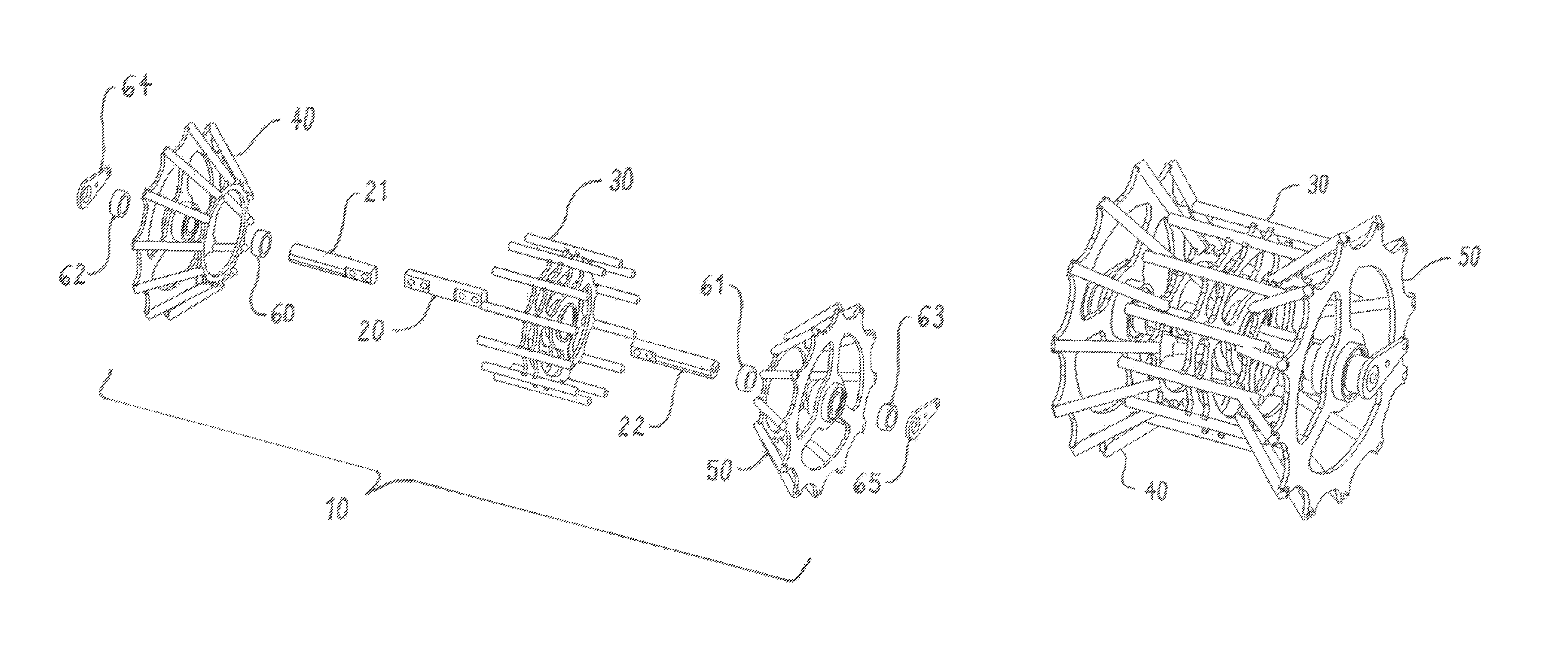
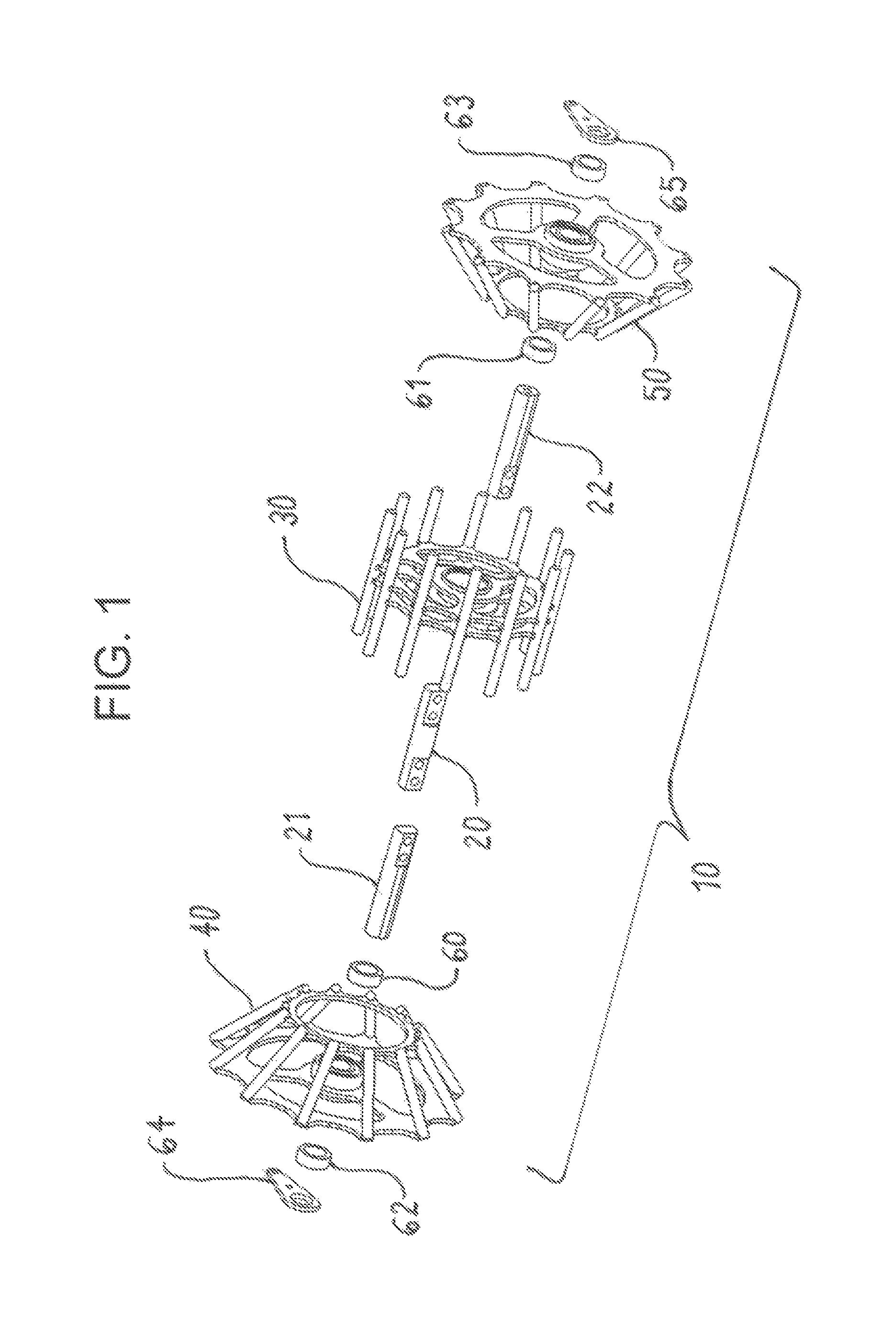
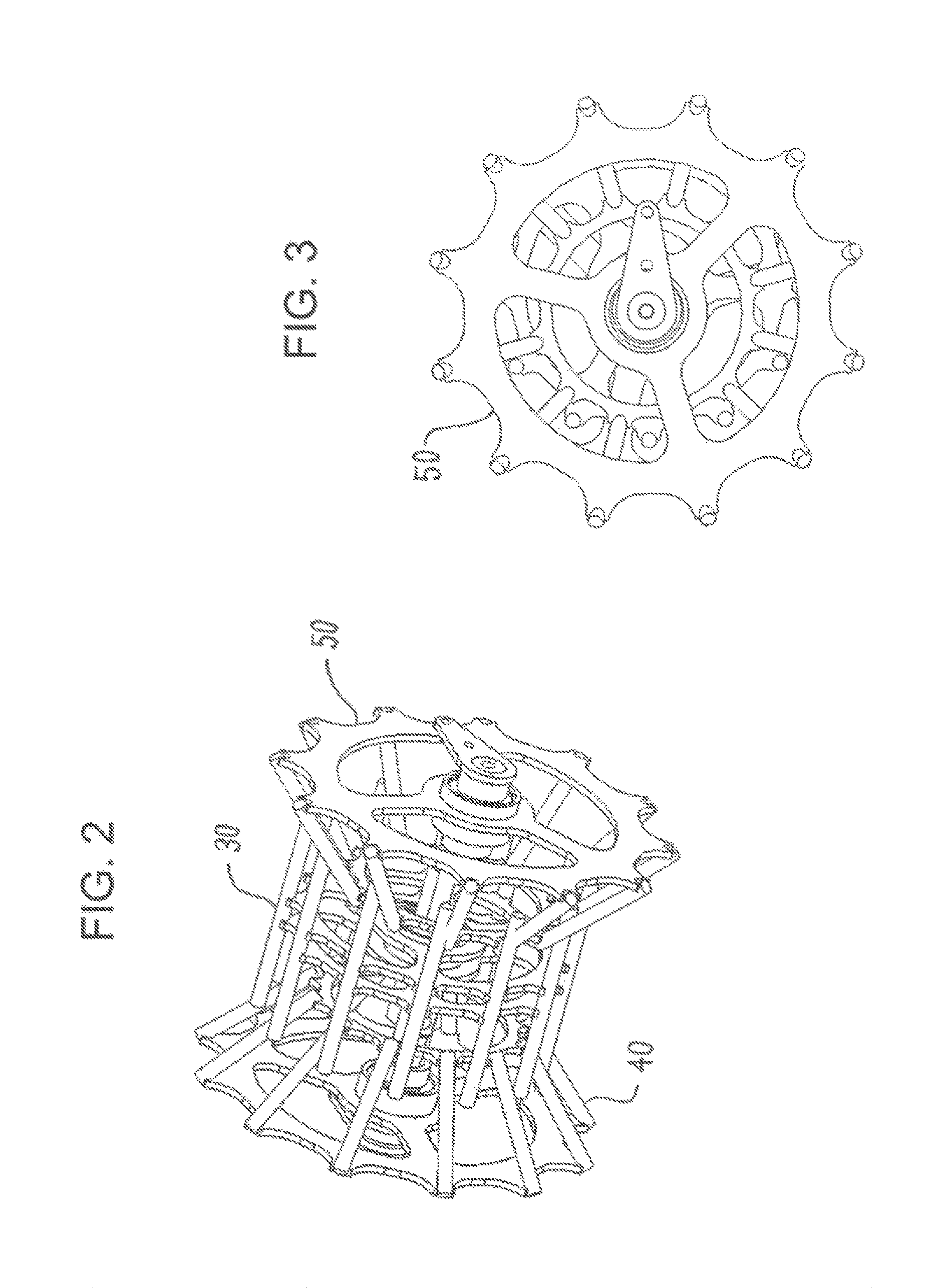
[0020]This invention is best understood by reference to the drawings. Referring first to FIGS. 1 to 5, the preferred embodiment of the tamping wheel 10 of this invention comprises a center spindle 20, a left spindle 21, a right spindle 22, a center basket 30, a left conical basket 40, a right conical basket 50, a left inner collar 60, a right inner collar 61, a left outer collar 62, a right outer collar 63, a left mounting bracket 64, and a right mounting bracket 65. The left conical basket and right conical basket are more precisely “frustoconical” in shape (a frustum is a cone with its upper end cut off by a plane parallel to the base). However, the term “conical” is used herein for simplicity. The components of the tamping wheel are all made of durable malleable materials, preferably steel. The components of the tamping wheel are discussed in detail below.

[0021]2. The Spindles

[0022]Referring now to FIGS. 6 and 7, the tamping wheel contains a cente...


PUM


Abstract

An adjustable tamping wheel forms a berm of a desired cross section over a recently filled trench. The tamping wheel contains a center spindle, an offset left spindle, an offset right spindle, a freely rotating center basket on the center spindle with transverse tamping members, a freely rotating left basket on the left spindle with inwardly converging transverse tamping members, and a freely rotating right basket on the right spindle with inwardly converging transverse tamping members.

Description

CROSS-REFERENCE TO RELATED APPLICATION[0001]This application claims the benefit of U.S. Provisional Application Ser. No. 61 / 937,753, Feb. 10, 2014.FIELD OF THE INVENTION[0002]This invention relates to farming. More particularly, this invention relates to row units for the tillage, planting, and fertilization of farmland.BACKGROUND OF THE INVENTION[0003]It is well known that crops such as corn and soybeans grow best in soil that is loose, rich in nutrients, and free of debris. After a crop is harvested, the soil is often compacted, depleted of nutrients, and full of crop residue and other debris. To restore the soil to optimal conditions, the soil is often tilled immediately before planting. Tilling is also known as cultivating or plowing (also spelled “ploughing”). The soil may also be tilled immediately after harvest. The conventional method of tillage is to treat the entire field. More recently, it has become popular to treat only the narrow strips of soil that will contain the se...

Claims


Application Information

Patent Timeline
IPC IPC(8): A01C5/06
CPCA01C5/066A01C5/068
Inventor ROSENBOOM, LYN A.
Owner ROSENBOOM LYN A
Why Eureka
Try Eureka