
Computing device, method, and program for distributing computational load

a computing load and computing device technology, applied in the field of computing load distribution, can solve the problems of increasing the complexity of the algorithms executed by global/centralised controllers in order to meet energy efficiency targets, increasing energy costs, and increasing the overall energy consumption caused by computing load and associated support mechanisms, so as to reduce the overall energy consumption caused by handling computing load and the associated support mechanisms, and achieve the effect of reducing the overall energy consumption caused by computing load and the removal of more efficiently

Inactive Publication Date: 2016-12-13
FUJITSU LTD
View PDF10 Cites 0 Cited by
  • Summary
  • Abstract
  • Description
  • Claims
  • Application Information

AI Technical Summary

Benefits of technology

This approach enables efficient load migration, reduces energy consumption by ensuring nodes operate at full capacity or are powered down, achieving significant energy savings and scalable performance without the need for centralized control, and allows for quick VM migration and efficient cooling resource allocation.

Problems solved by technology

Besides, energy costs are a major fraction of the operating costs of data centres, becoming almost as important as the cost of the facilities and equipment.
Complex algorithms exist for calculating and realising optimum distribution of computational load among devices and correct operating settings of cooling equipment.
As the size of data centres grows, and their increasing importance in IT infrastructure provision increases, the complexity of the algorithms executed by the global / centralised controllers in order to meet energy efficiency targets also increases.
In addition, the one or more computing devices per designated position which execute the process may be restricted to those computing devices which currently have load.
However, if a computing device is not hosting any load when it comes to that computing device's turn to execute the process, that computing device does not execute the process, and the process is executed by the next computing device in the order which has load to transfer.

Method used


Image

  • Computing device, method, and program for distributing computational load
  • Computing device, method, and program for distributing computational load
  • Computing device, method, and program for distributing computational load

Examples


Embodiment Construction

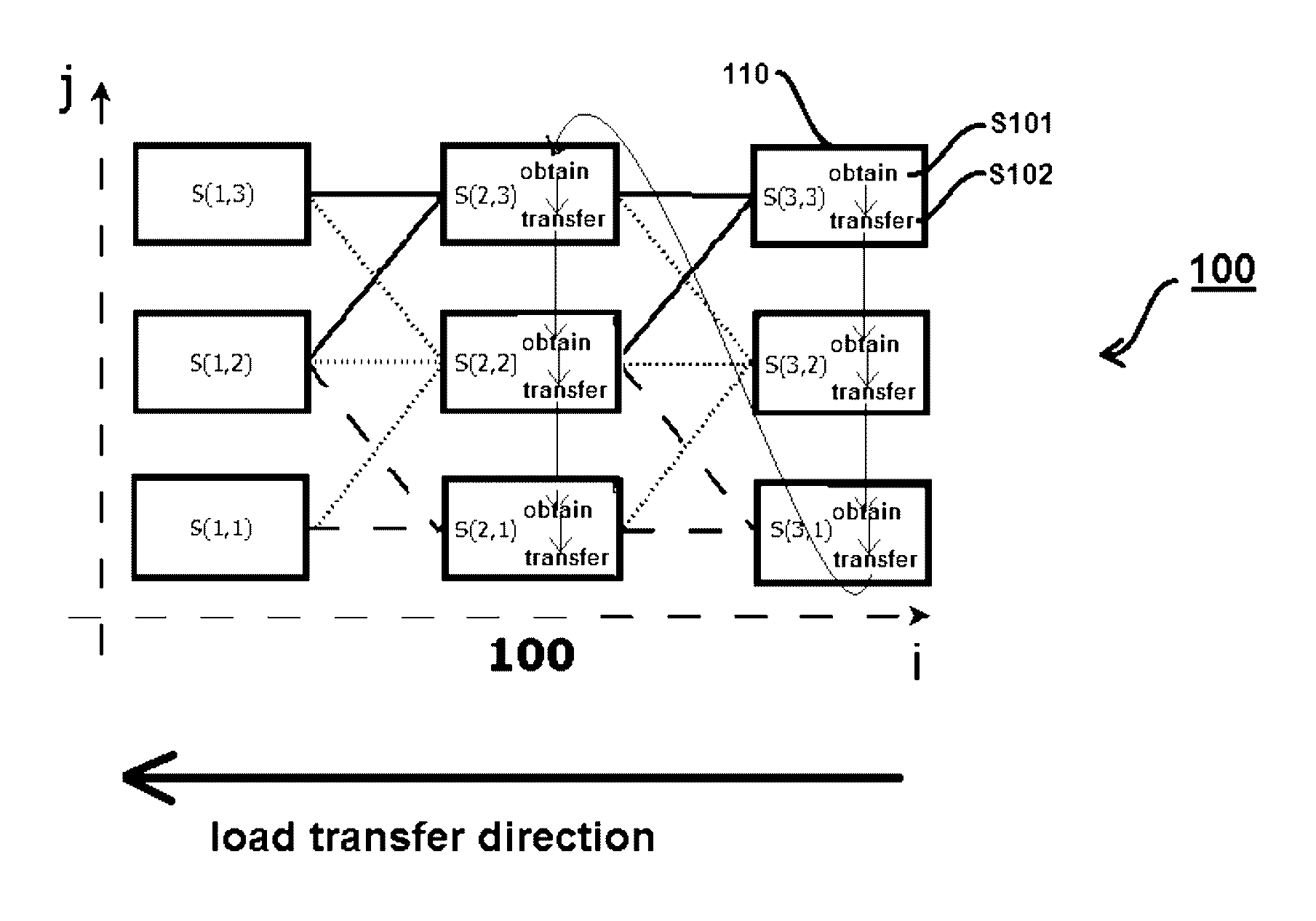
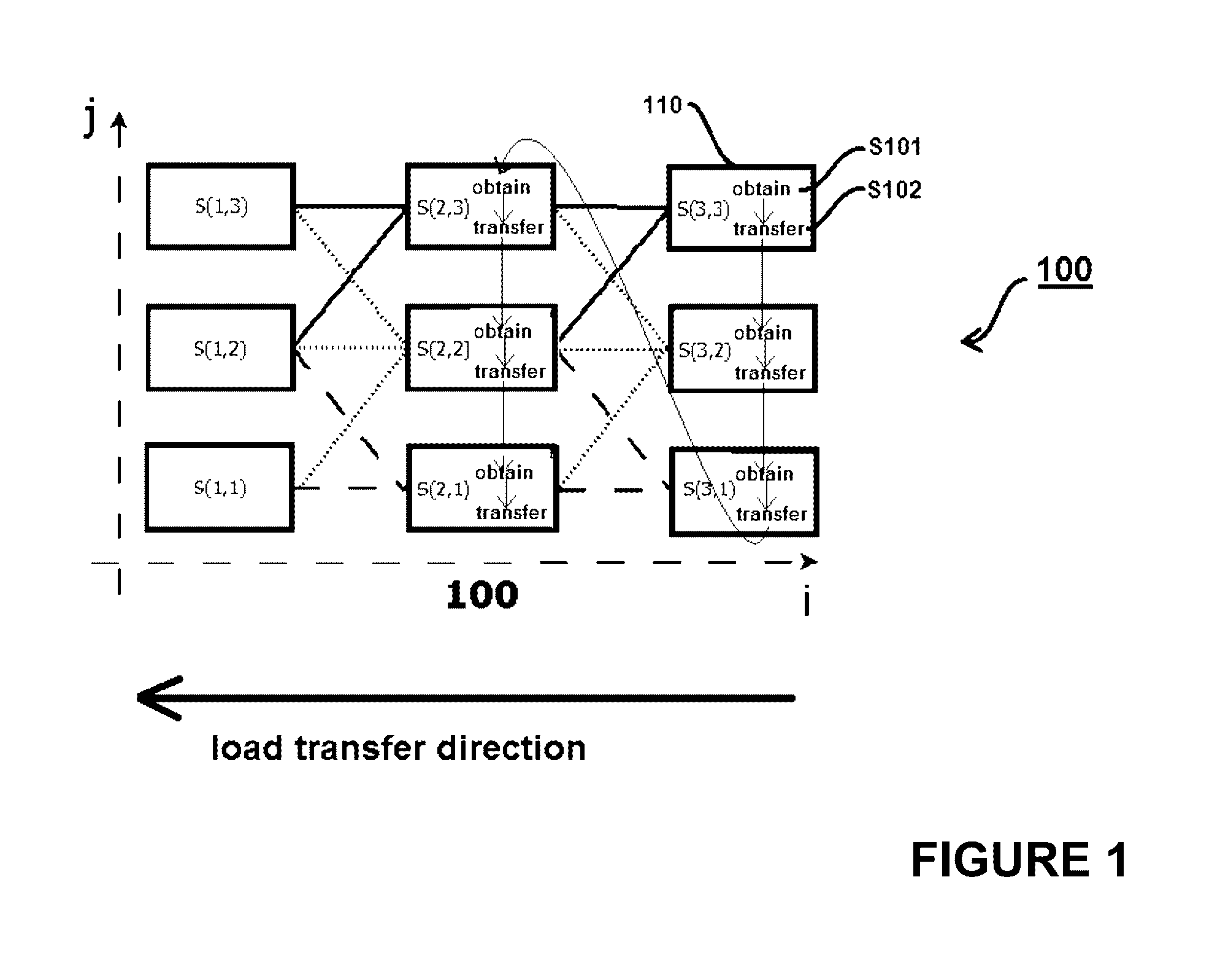
[0064]FIG. 1 is a schematic representation of an array of designated positions 100 of a plurality of interconnected computing devices in which a method embodying the present invention is performed. The method steps S101-S102 are overlaid onto the schematic illustration of the plurality of interconnected computing devices. Each computing device 110 in the plurality of interconnected computing devices has a designated position in each dimension of a 2-dimensional array of designated positions 100.

[0065]The method steps are overlaid onto the schematic representation of the computing devices, and the arrows linking the steps indicates the steps being performed sequentially. The process of obtaining S101 and transferring S102 is performed individually and in turn by one or more computing devices per designated position in a series of designated positions in one dimension of the n-dimensions. In the particular example of FIG. 1, the series of designated positions in one dimension of the n...


PUM


Abstract

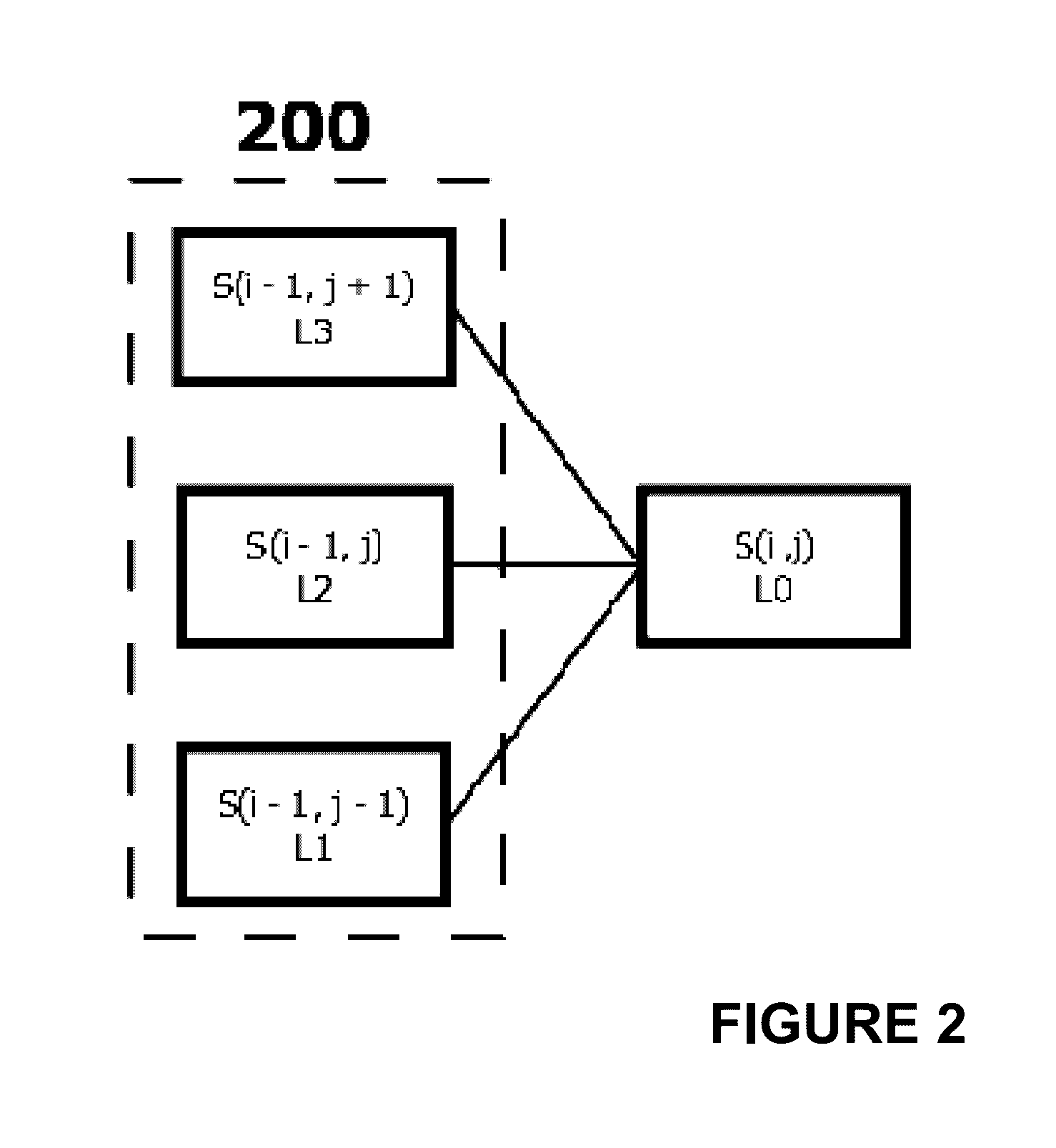
A method for distributing load among interconnected computing devices, each computing device having a designated position in each dimension of an array of designated positions, the method comprising, individually, at one or more computing devices per position in a series of positions in one dimension of n-dimensions, in which one dimension and one direction is assigned as a load transfer direction, executing a process including: obtaining an indication of current capacity for additional load at each member of a group of computing devices from among the computing devices; transferring load from the executing computing device to a member of the group at which it is indicated that there is capacity for additional load; where membership of the group is restricted to a computing device on the load transfer direction side of the executing computing device in the one dimension.

Description

CROSS REFERENCE TO RELATED APPLICATIONS[0001]This application claims the benefit of European Application No. 13186667.5, filed Sep. 30, 2013, the disclosure of which is incorporated herein by reference.BACKGROUND OF THE INVENTION[0002]This invention lies in the technical field of computational load distribution in networked computing environments. In particular, the invention lies in the field of green data centre technology, and energy-efficient data center load distribution.[0003]Given their enormous electrical power consumption and associated carbon footprint, computing environments such as data centres are natural targets for techniques aimed at improving their energy efficiency and reducing their impact on the environment. This is especially true in light of the explosive growth in the number of data centres and the increasing dependence of our society on the information technology and computing services provided by them. Besides, energy costs are a major fraction of the operat...

Claims


Application Information

Patent Timeline
Patent Type & Authority Patents(United States)
IPC IPC(8): H04L29/08G06F1/32G06F9/50
CPCH04L67/10G06F1/32G06F9/50H04L67/1002G06F9/5083G06F1/329Y02D10/00H04L67/1001
Inventor ALBORNOZ, JOSE
Owner FUJITSU LTD
Learn More