Tower sector frame antenna mount

a technology for tower sector frames and antenna mounts, applied in girders, joists, lintels, etc., can solve the problems of complex structure structure, high potential combined and the development of tension, compression and bending forces within individual frame members, so as to minimize the overall effective projected wind load area of the frame and increase the rigidity of the entire frame

Inactive Publication Date: 2007-11-15
CARLISLE DONALD C +1
View PDF7 Cites 58 Cited by
  • Summary
  • Abstract
  • Description
  • Claims
  • Application Information

AI Technical Summary

Benefits of technology

[0007] The present invention improves existing frames by utilizing light weight aluminum mated extrusion designs which restrict the rotation and translation of individual structural members within the frame. The improved frame is constructed of custom designed tubular sections which form the upper and lower beams of the frame. Tubular column members are used to connect the upper and lower beams establishing the appropriate vertical spacing between the beam members. Additional tubular members are installed at an angle in a fixed angular orientation relative to the upper and lower beams forming truss style webbing, which increases the rigidity of the entire frame. The interior cross-sections of the tubes of the tubular members are designed to mate with extruded inserts in a manner which limits any relative rotation between connected components. Additionally, bolts pass through the tube and the internal mated extrusion establishing a fixed connection that can neither rotate nor translate. Since the connections are made with internal fittings the round external cross-section profiles of the structural shapes are maintained, reducing and thus minimizing the overall effective projected wind load area of the frame.

Problems solved by technology

When fixed connections between components are used, the application of loads results in the development of tension, compression and bending forces within individual members of the frame.
Open structural shapes such as angles and channels are highly susceptible to combined compression and bending.

Method used


Image

  • Tower sector frame antenna mount
  • Tower sector frame antenna mount
  • Tower sector frame antenna mount

Examples


Embodiment Construction

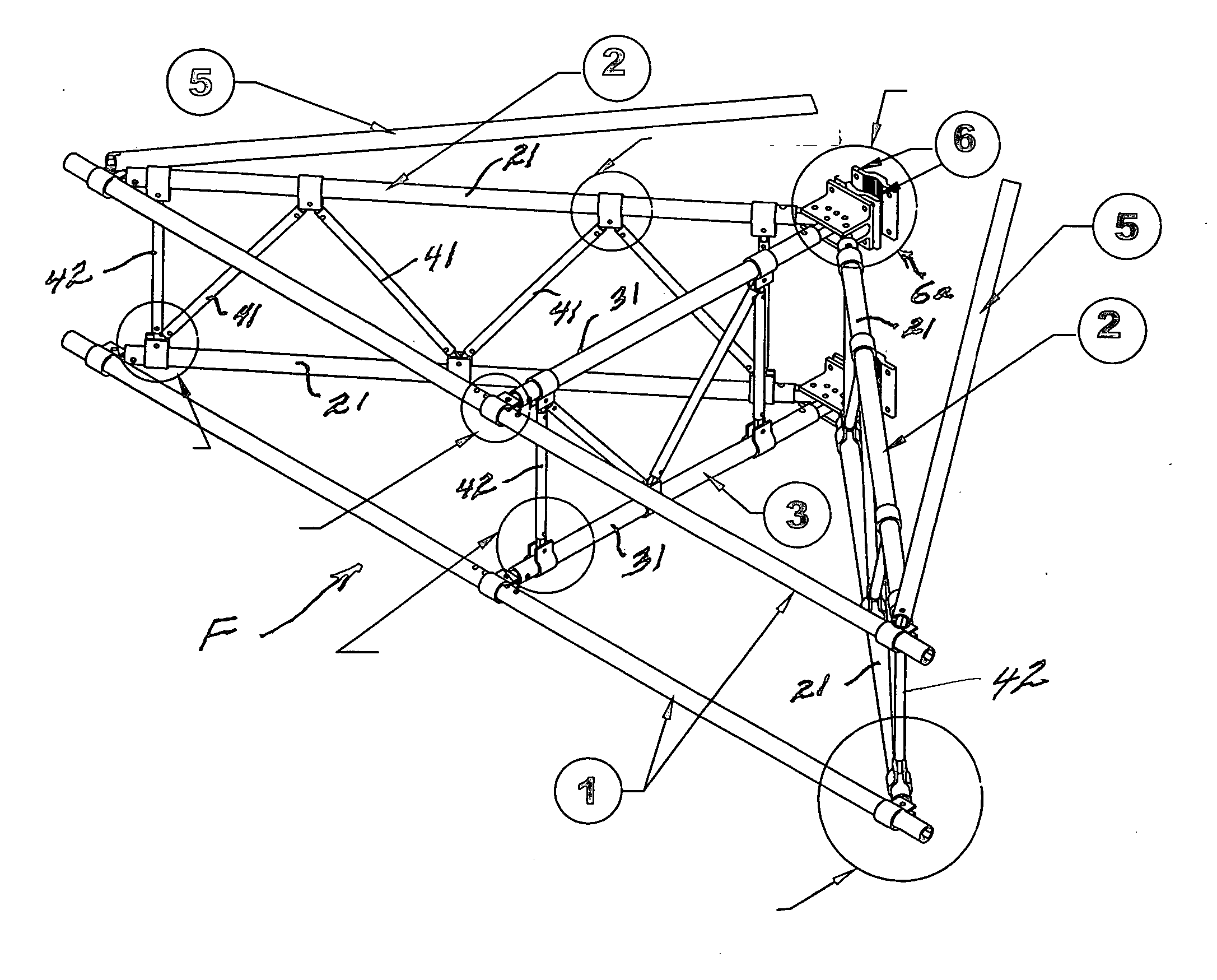
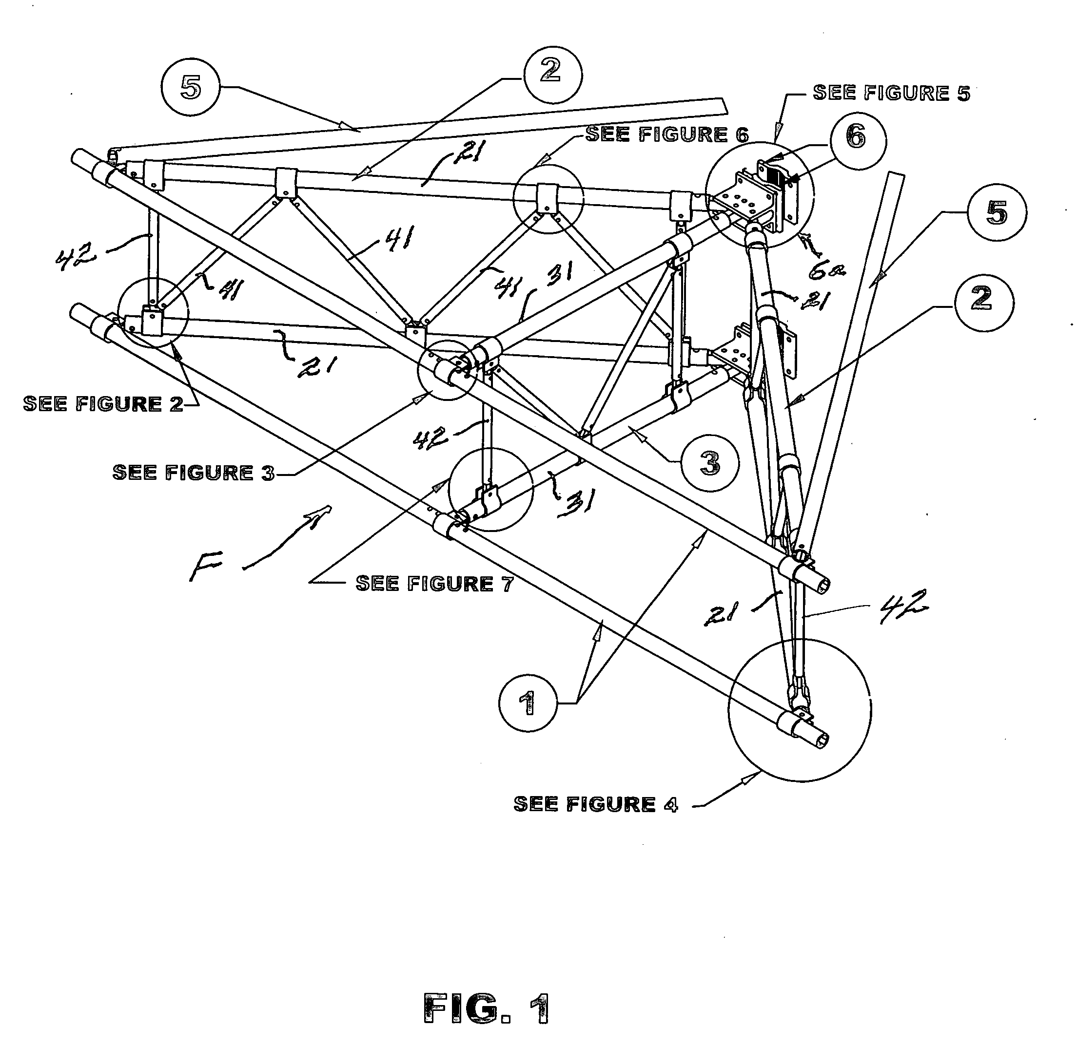
[0030] The present art overcomes prior limitations by providing a light weight sector wireless communications antenna mounting frame with fixed inter-component structural connections that resist rotation and translation while maintaining the round tubular outside cross-sectional profile of the structural components. The tubular outside cross-sectional use of round profile components and connections results in a low effective projected wind load area, which in turn reduces the wind load effects transferred to the connected communications tower.

[0031] Turning to FIG. 1, the communication antennas (not shown) are mounted to the front face tubular beam members 1 of the sector front frame F. The sector frame is attached to a communications tower by way of clamping device bracket 6a. Tubular or angular tower members are sandwiched between opposing members of the clamping devices 6. Attachment hardware, in the form of threaded bolts, pass through horizontally oriented holes in the clampin...


PUM


Abstract

An improvement for an aluminum lattice sector frame of the type used for supporting wireless communications antennas and designed to be mounted on a communication tower, is provided. Mating extruded components are used to provide fixed connections which restrict relative rotation and translation between connected parts while presenting a round tubular outside cross-sectional profile thereby reducing the effective projected wind load area of the frame. The fixed component connections greatly reduce the overall deflection of the frame under applied combined dead, wind and ice loading.

Description

FIELD OF INVENTION [0001] This invention relates to mounting system frames used to support wireless communications antennas. Such mounting frames are used to position the communications antennas at an appropriate location to allow the antennas to function. BACKGROUND OF THE INVENTION [0002] This invention relates to mounting system frames used to support wireless communications antennas. Such mounting frames are used to position the communications antennas at an appropriate location to allow the antennas to function. The most common application is to mount the antenna frame to a communications tower. The frame is designed to support the loads applied to the antennas as well as to the frame itself and then transfer the loads into the supporting communications tower. Typical loads that must be considered are dead gravity loads (e.g., self weight, and man loads and ice accumulation), wind, and ice accumulated on the antennas and the frame and dynamic loads such as wind effects. Various...

Claims


Application Information

Patent Timeline
Patent Type & Authority Applications(United States)
IPC IPC(8): E04C3/02
CPCH01Q1/1242
Inventor CARLISLE, DONALD C.FARIES, GUY L.
Owner CARLISLE DONALD C
Why Eureka
Try Eureka