Vehicle body front structure

a front structure and vehicle technology, applied in the direction of roofs, transportation and packaging, vehicle arrangements, etc., can solve the problems of difficult placement of in-vehicle parts into this space, small flexibility in layout, and the front side frame and the member are separated, so as to improve the load propagation efficiency to the bending point, the effect of improving the strength and rigidity of the extension par

Active Publication Date: 2013-09-19
HONDA MOTOR CO LTD
View PDF0 Cites 60 Cited by
  • Summary
  • Abstract
  • Description
  • Claims
  • Application Information

AI Technical Summary

Benefits of technology

[0039]According to such a structure, it is possible to improve strength and rigidity of the extension part by providing the bead in the extension part. In addition, it is possible to obtain a structure whose strength and rigidity are improved further by the closed cross-section being formed between the bead and front side frame. Thereby, it is possible to improve load propagation efficiency to the bending point.
[0040]According to the present invention, it is possible to provide a vehicle body front structure that can propagate the impact load at the time of a narrow offset collision reliably to the front side frame and has sufficient space between the front side frame and the member.

Problems solved by technology

However, since the invention described in JP 4,680,784 B directly fixes the front side frame and the member together, the space between the front side frame and the member are inevitably small and thus it is difficult to place in-vehicle parts into this space.
As a result, restrictions arise in the locations at which the in-vehicle parts are placed and therefore there is a problem of small flexibility in the layout.

Method used


Image

  • Vehicle body front structure
  • Vehicle body front structure
  • Vehicle body front structure

Examples


Embodiment Construction

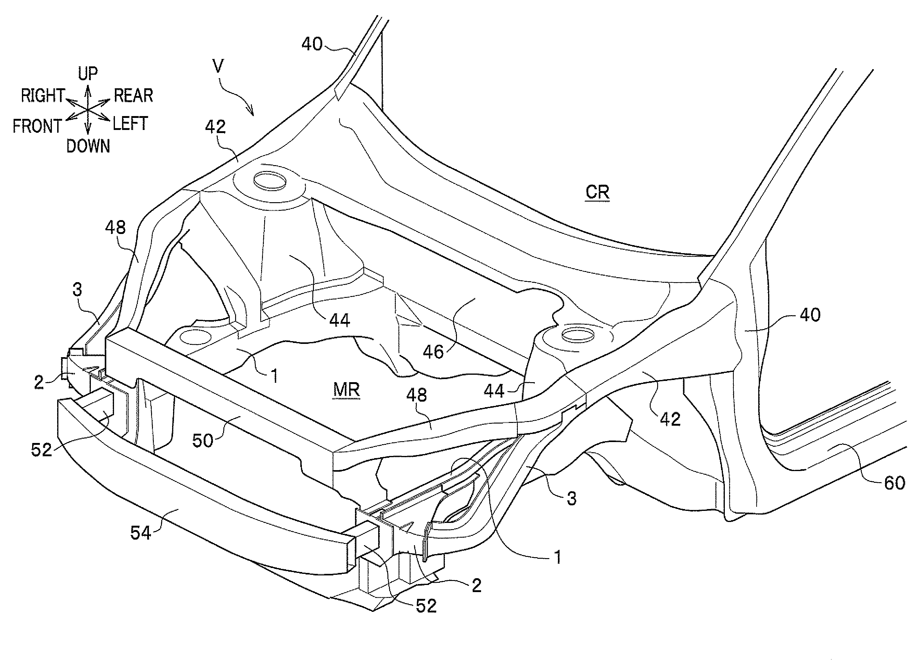
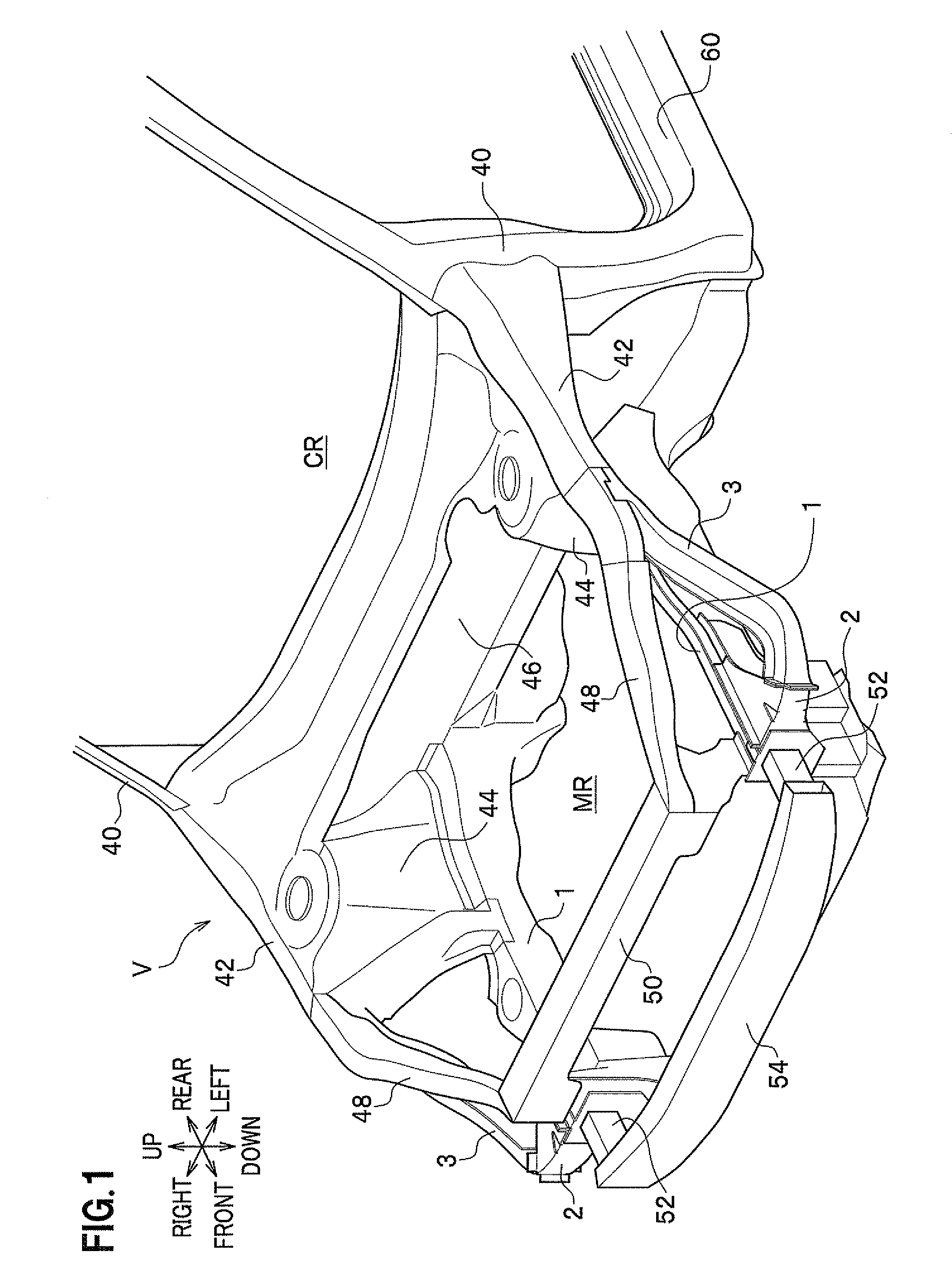
[0051]Next, embodiments of the present invention will be described in detail with reference to the drawings as appropriate. It should be noted that “front” and “rear”, and “up” and “down” shown with arrows in the drawings indicate the vehicle front-rear direction and the vehicle body up-down direction, respectively, and “right” and “left” indicates the left-right direction (vehicle width direction) when viewed from the driver's seat. In addition, in this embodiment, a longitudinal cross-section indicates a vertical cross-section and a traverse cross-section indicates a horizontal cross-section.

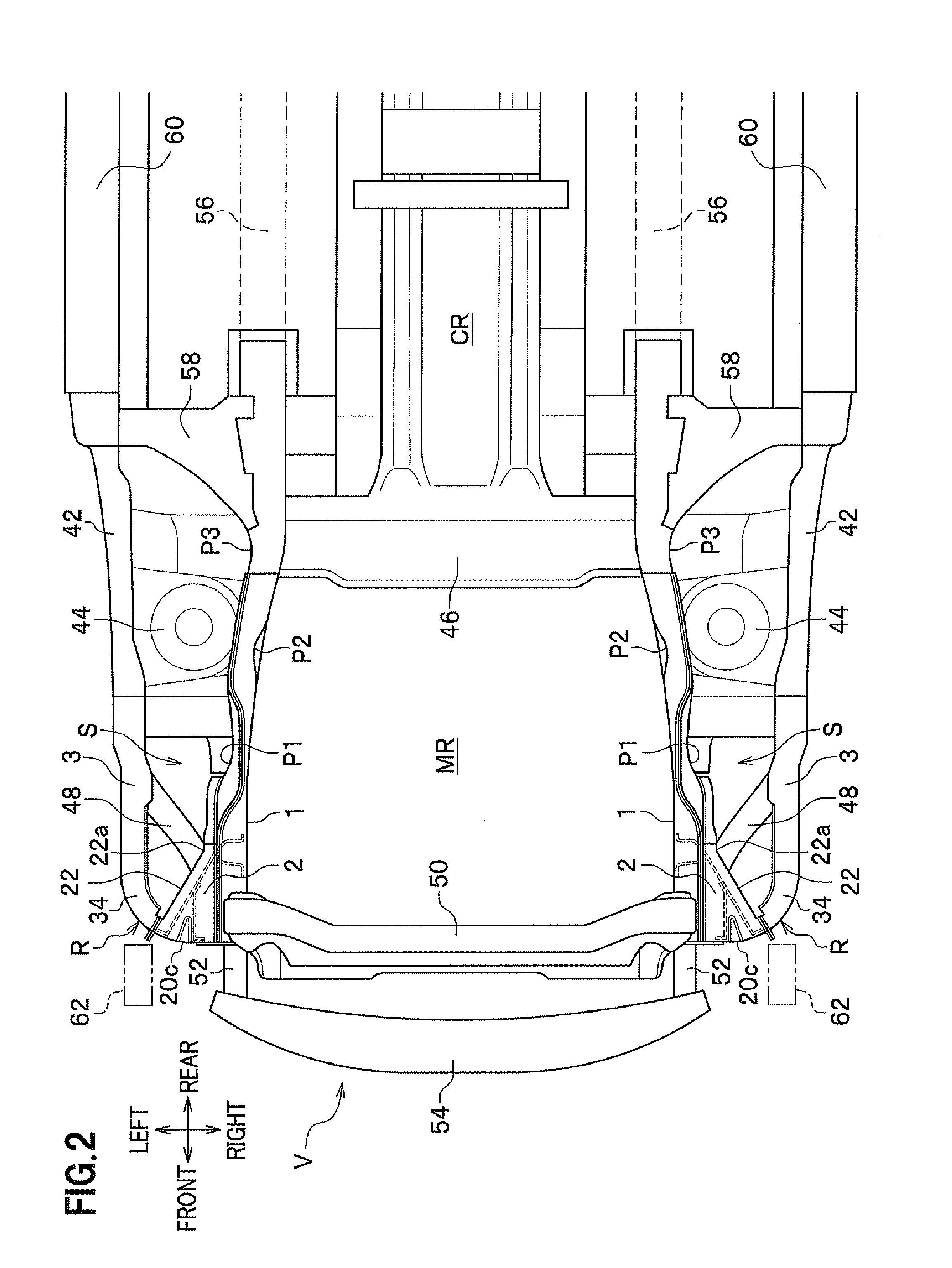
[0052]FIG. 1 is a perspective view of the front part of the vehicle body to which the vehicle body front structure according to an embodiment of the present invention is applied. FIG. 2 is a bottom view of the front part of the vehicle body shown in FIG. 1. As shown in FIG. 1, a vehicle V includes: a pair of front side frames 1, 1 placed at both the right and left sides; and a pair of right an...


PUM


Abstract

A vehicle body front structure includes: a front side frame; a lower member placed at an outer side of the front side frame in the vehicle width direction; and a gusset placed between the front side frame and the lower member. The front side frame includes a first bending point which absorbs an impact load by being bent by receiving impact load upon a collision of the vehicle. An inner side of the gusset in the vehicle width direction is joined to the outer side of the front side frame in the vehicle width direction and extends from a front end of the front side frame to a first bending point. A tapered part which is inclined toward the front side frame as extending backward from the front end of the gusset is formed in an outer side of the gusset in the vehicle width direction.

Description

CROSS REFERENCE TO RELATED APPLICATION[0001]This application claims the priority of Japanese Applications No. 2012-062813, filed on Mar. 19, 2012 and 2012-068814 filed on Mar. 19, 2012, the entire specification, claims and drawings of which are incorporated herewith by reference.BACKGROUND OF THE INVENTION[0002]1. Field of the Invention[0003]The present invention relates to a vehicle body front structure.[0004]2. Description of the Related Art[0005]A conventional vehicle body front structure, including: a front side frame extending along a vehicle front-rear direction; a member placed at an outer side of the front side frame in a vehicle width direction; and a connecting component for connecting the front side frame and the member, is known (for example, see JP 3,599,327 B).[0006]Meanwhile, the vehicle body is desired to absorb impact energy by propagating an impact load to the front side frame in addition to the member such that the shape of the front side frame is deformed at the ...

Claims


Application Information

Patent Timeline
Patent Type & Authority Applications(United States)
IPC IPC(8): B62D21/15
CPCB62D21/152B62D25/085B62D21/155B62D25/082
Inventor OHNAKA, RYOTAGUCHI, YOSHINORIHISAZUMI, MAKOTOHASHIMOTO, NAOYUKI
Owner HONDA MOTOR CO LTD
Why Eureka
Try Eureka