
Radio network node and method therein

a radio network and node technology, applied in the field of radio network nodes, can solve the problems of poor utilization of pa resources, inability to apply real-time methods, and complicated optimization problems, and achieve the effect of improving the utilization rate of power amplifiers

Active Publication Date: 2016-12-13
TELEFON AB LM ERICSSON (PUBL)
View PDF6 Cites 2 Cited by
  • Summary
  • Abstract
  • Description
  • Claims
  • Application Information

AI Technical Summary

Benefits of technology

The patent aims to enhance the performance of a radio network node that uses multiple antenna ports in a network. The invention uses information about the frequency selectivity and time variation of the radio channel to improve the utilization of power amplifiers. This is done by taking into account the utilization factor of power amplifiers while scheduling user equipment. The technical effect of the invention is better performance of the radio network node with improved power amplifier utilization.

Problems solved by technology

However, this leads to a more complicated optimization problem which typically does not have a closed form solution.
Therefore, one has to resort to numerical optimization which may render a real-time application of the method impractical.
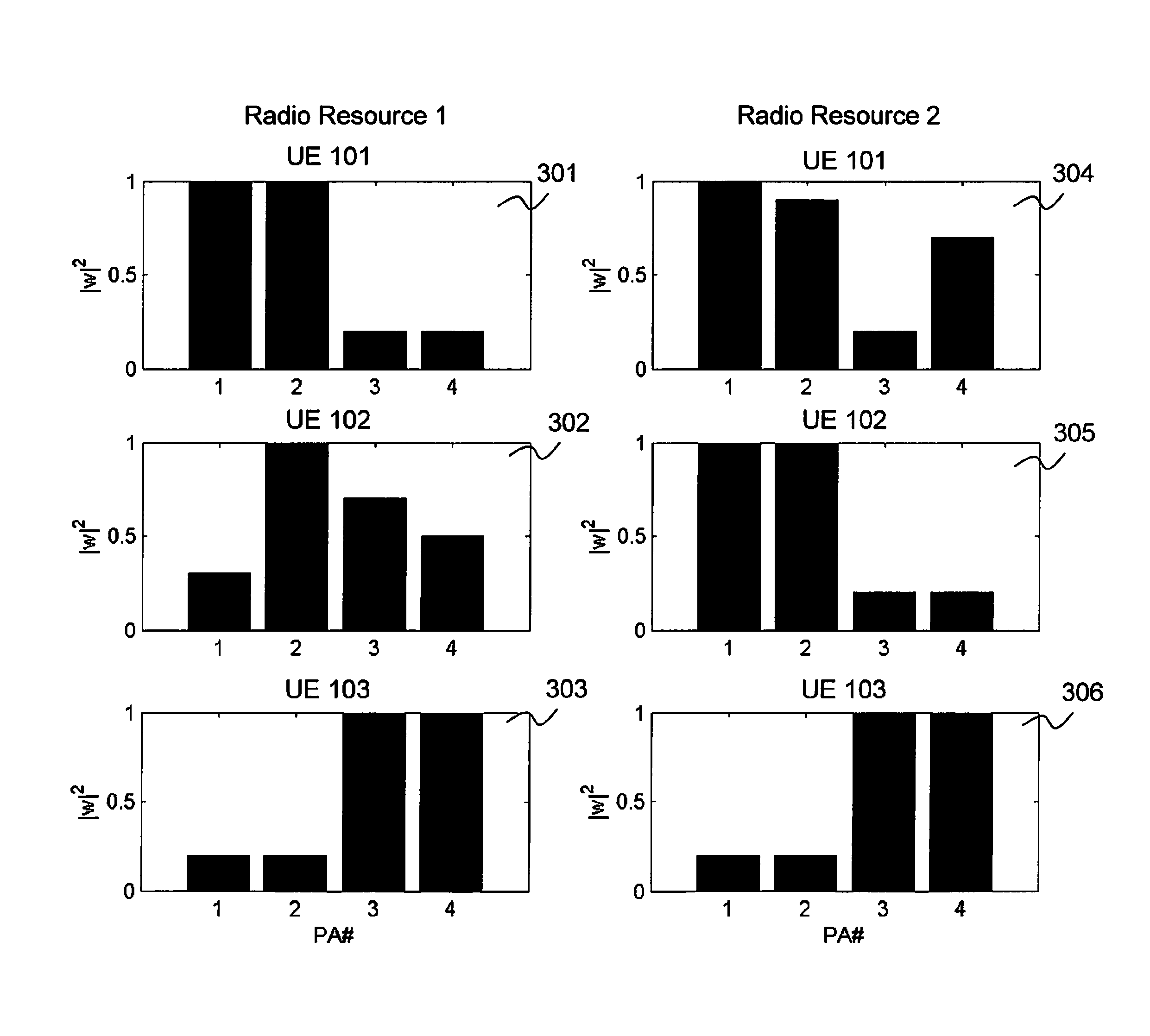
A problem with existing solutions is that the optimal weights do not have equal amplitude which will lead to poor utilization of the available PA resources.
This means that if the transmit weights do not have equal amplitude, some of the radio branches will not transmit with full power.
The PAs in these branches will then also work at a load where they have poor efficiency.
This results in a reduced performance of the communication within the radio communications network.

Method used


Image

  • Radio network node and method therein
  • Radio network node and method therein
  • Radio network node and method therein

Examples


Embodiment Construction

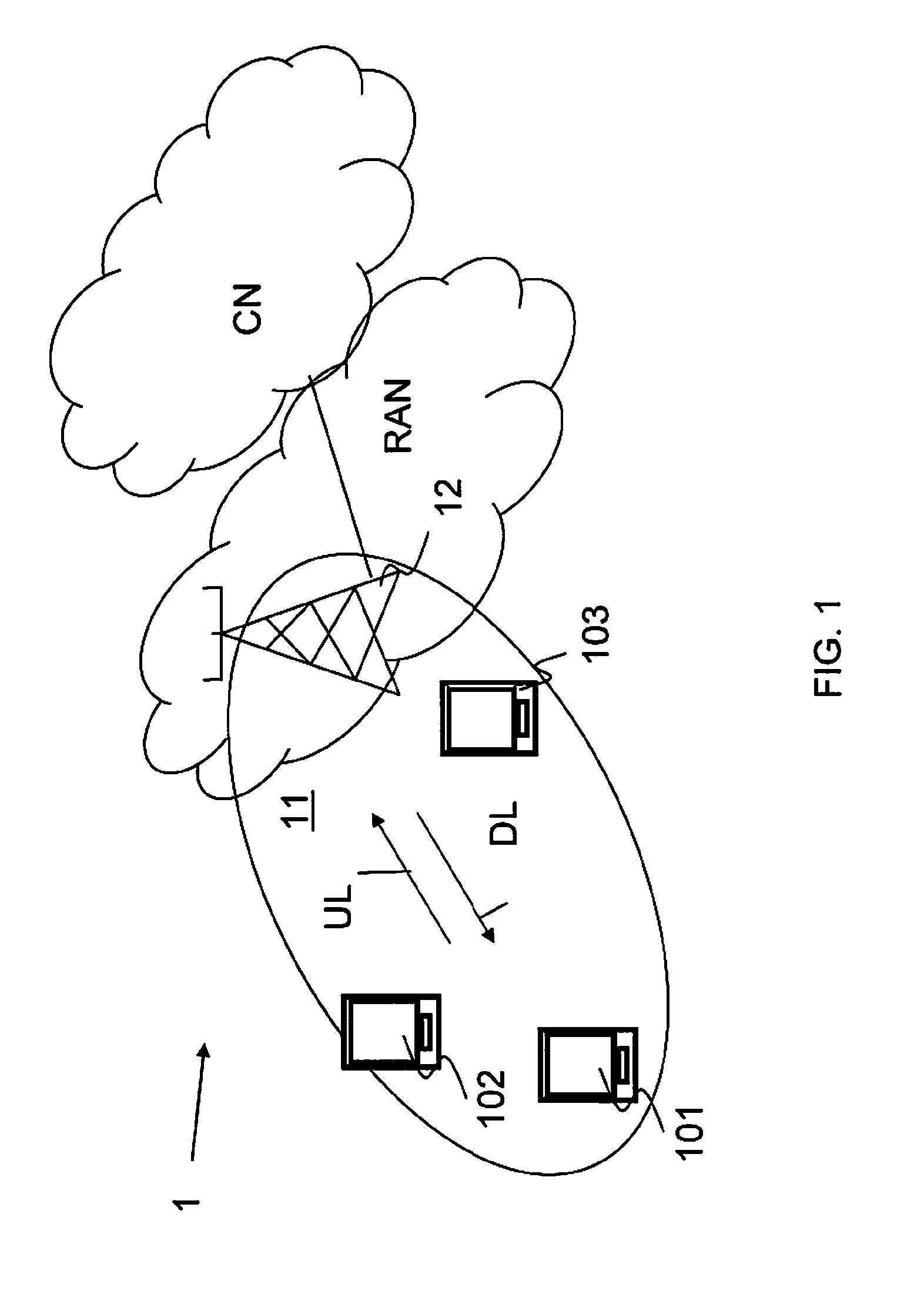
[0017]FIG. 1 is a schematic overview depicting a radio communications network 1 according to embodiments herein. The radio communications network 1 may be an LTE-advanced network, an LTE network, Universal Terrestrial Radio Access Network (UTRAN)-General Packet Radio Service (GPRS) network, a WCDMA network, a Code Division Multiple Access (CDMA) 2000 network, an Interim Standard 95 (IS-95) network, a Digital-Advanced Mobile Phone Service (D-AMPS) network but is exemplified below as an LTE network.

[0018]The radio communications network 1 comprises a radio network node 12 exemplified in FIG. 1 as a radio base station in a Radio Access Network (RAN). The RAN provides access to a Core Network (CN). The radio network node 12 serves or controls radio resources over a geographical area forming a cell 11.

[0019]User equipments, a first user equipment 101, a second user equipment 102, and a third user equipment 103, are served in the cell 11 by the radio network node 12. It should be understo...


PUM


Abstract

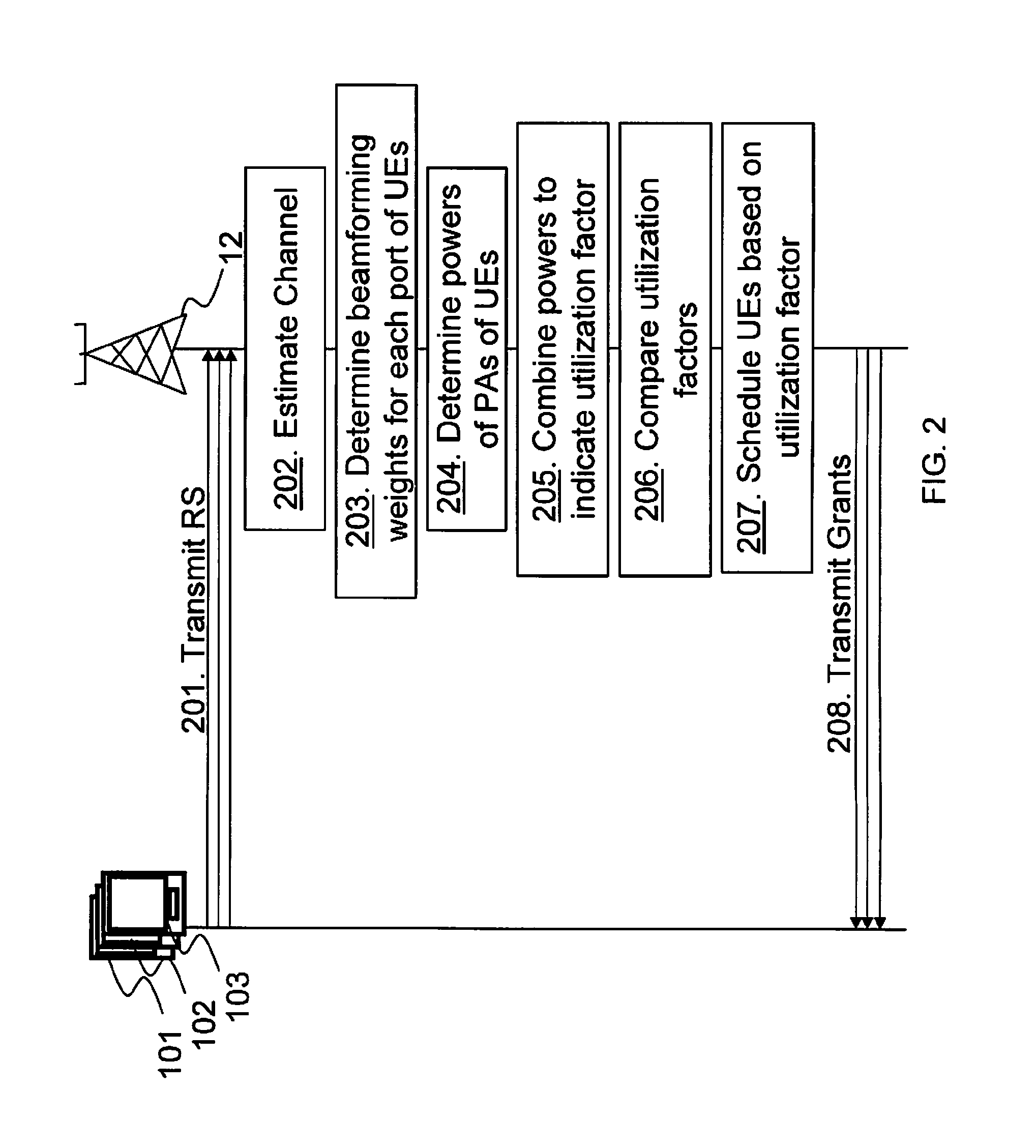
Embodiments herein relate to a radio network node for scheduling a radio resource within a radio communications network. The radio network node comprises at least two antenna ports over which communication is performed using a respective power amplifier over each antenna port out of the at least two antenna ports. The radio network node determines a utilization factor of power of each power amplifier when a first user equipment is assigned to the radio resource. The radio network node further determines a utilization factor of power of each power amplifier when a second user equipment is assigned to the radio resource. The radio network node then schedules the first user equipment or the second user equipment to the radio resource based on the determined utilization factors.

Description

[0001]This application is a 35 U.S.C. §371 national phase filing of International Application No. PCT / SE2012 / 050048, filed Jan. 20, 2012, the disclosure of which is incorporated herein by reference in its entirety.TECHNICAL FIELD[0002]A radio network node and a method therein. In particular, embodiments herein relate to scheduling a radio resource in a radio communications network.BACKGROUND[0003]In today's radio communications networks a number of different technologies are used, such as Long Term Evolution (LTE), LTE-Advanced, Wideband Code Division Multiple Access (WCDMA), Global System for Mobile communications / Enhanced Data rate for GSM Evolution (GSM / EDGE), Worldwide Interoperability for Microwave Access (WiMax), or Ultra Mobile Broadband (UMB), just to mention a few possible implementations. A radio communications network comprises radio network nodes such as radio base stations providing radio coverage over at least one respective geographical area forming a cell. The cell d...

Claims


Application Information

Patent Timeline
IPC IPC(8): H04W52/34H04W72/04H04L5/00H04B7/04H04B7/06
CPCH04B7/0426H04B7/0452H04B7/0465H04B7/068H04W52/346H04B7/0617H04L5/0023H04L5/0037H04W72/0446H04W72/0453H04W72/0473
Inventor ATHLEY, FREDRIKCOLDREY, MIKAELPETERSSON, SVEN
Owner TELEFON AB LM ERICSSON (PUBL)
Learn More